- 您现在的位置:买卖IC网 > PDF目录136845 > SBF545 (LITE-ON ELECTRONICS INC) 5 A, 45 V, SILICON, RECTIFIER DIODE, TO-220AC PDF资料下载
参数资料
| 型号: | SBF545 |
| 厂商: | LITE-ON ELECTRONICS INC |
| 元件分类: | 整流器 |
| 英文描述: | 5 A, 45 V, SILICON, RECTIFIER DIODE, TO-220AC |
| 封装: | PLASTIC, ITO-220AC, 2 PIN |
| 文件页数: | 1/2页 |
| 文件大小: | 72K |
| 代理商: | SBF545 |
F
A
E
B
C
G
I
D
2
1
H
L
N
J
K
PIN
M
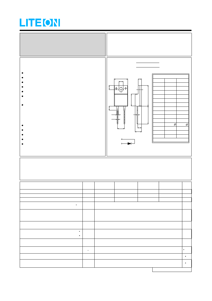
ITO-220AC
All Dimensions in millimeter
ITO-220AC
DIM.
MIN.
MAX.
A
C
D
E
F
G
H
B
15.50
16.50
10.40
10.0
3.00
3.50
9.30
9.00
2.90
3.60
13.46
14.22
1.15
1.70
0.75
5.33
N
M
L
K
J
I
1.00
4.83
0.70
0.45
3.00
3.30
4.36
4.77
2.48
2.80
2.50
PIN 1
PIN 2
SBF530 thru SBF545
MAXIMUM RATINGS AND ELECTRICAL CHARACTERISTICS
Ratings at 25
ambient temperature unless otherwise specified.
℃
Single phase, half wave, 60Hz, resistive or inductive load.
For capacitive load, derate current by 20%
FEATURES
Metal of silicon rectifier,majority carrier conducton
Guard ring for transient protection
Low power loss, high efficiency
High current capability, low VF
High surge capacity
Plastic package has UL flammability classification
94V-0
For use in low voltage,high frequency inverters,free
whelling,and polarity protection applications
MECHANICAL DATA
Case : ITO-220AC molded plastic
Polarity : As marked on the body
Weight : 0.06 ounces, 1.7 grams
Mounting position :Any
Max. mounting torque = 0.5 N.m (5.1 Kgf.cm)
NOTES : 1. 300us Pulse Width, 2% Duty Cycle.
2. Measured at 1.0MHz and applied reverse voltage of 4.0V DC.
3.Thermal Resistance Junction to Case.
VRMS
VDC
VRRM
I(AV)
IFSM
VF
Maximum Average Forward
Rectified Current (See Fig.1)
@TC
=115 C
Peak Forward Surge Current
8.3ms single half sine-wave
superimposed on rated load
Maximum Recurrent Peak Reverse Voltage
Maximum RMS Voltage
Maximum DC Blocking Voltage
Maximum Forward Voltage
at 5A DC (Note 1)
5
150
0.55
TJ
Operating Temperature Range
-55 to +125
C
TSTG
Storage Temperature Range
-55 to +150
C
Typical Thermal Resistance (Note 3)
R0JC
4
C/W
CJ
Typical Junction
Capacitance (Note 2)
350
pF
IR
@TJ =100 C
Maximum DC Reverse Current
at Rated DC Blocking Voltage
@TJ =25 C
0.5
50
mA
V
A
V
UNIT
V
CHARACTERISTICS
SYMBOL
SBF545
45
31.5
45
SBF540
40
28
40
SBF535
35
24.5
35
SBF530
30
21
30
SCHOTTKY BARRIER RECTIFIERS
REVERSE VOLTAGE - 30 to 45 Volts
FORWARD CURRENT - 5.0 Amperes
SEMICONDUCTOR
LITE-ON
REV. 1, Aug-2007, KTHC51
相关PDF资料 |
PDF描述 |
|---|---|
| SL83L | 8 A, 30 V, SILICON, RECTIFIER DIODE, DO-214AB |
| ST60100A | 20 A, 1000 V, SILICON, RECTIFIER DIODE, TO-3 |
| ST60100D | 20 A, 1000 V, SILICON, RECTIFIER DIODE, TO-3 |
| ST6020A | 20 A, 200 V, SILICON, RECTIFIER DIODE, TO-3 |
| ST6040D | 20 A, 400 V, SILICON, RECTIFIER DIODE, TO-3 |
相关代理商/技术参数 |
参数描述 |
|---|---|
| SBF-5B-100-G | 制造商:ROBNSN 功能描述: |
| SBFP405B | 制造商:SANYO 制造商全称:Sanyo Semicon Device 功能描述:UHF to C Band Low-Noise Amplifier Osc. Applications |
| SBFP405D | 制造商:SANYO 制造商全称:Sanyo Semicon Device 功能描述:SBFP405D |
| SBFP420B | 制造商:SANYO 制造商全称:Sanyo Semicon Device 功能描述:UHF to C Band Low Noise Amplifier, Oscillation Applications |
| SBFP420D | 制造商:SANYO 制造商全称:Sanyo Semicon Device 功能描述:UHF to C Band Low Noise Amplifier, Oscillation Applications |
发布紧急采购,3分钟左右您将得到回复。