- 您现在的位置:买卖IC网 > PDF目录16696 > SC-KIT-TBX (Linear Technology)TIMERBLOX SAMPLE KIT PDF资料下载
参数资料
| 型号: | SC-KIT-TBX |
| 厂商: | Linear Technology |
| 文件页数: | 3/30页 |
| 文件大小: | 0K |
| 描述: | TIMERBLOX SAMPLE KIT |
| 设计资源: | TimerBlox Designer |
| 特色产品: | TimerBlox? |
| 标准包装: | 1 |
| 系列: | TimerBlox® |
| 主要目的: | 计时,时钟振荡器 |
| 嵌入式: | 否 |
| 已用 IC / 零件: | LTC6990,LTC6991,LTC6992-1,LTC6993-2,LTC6994-1 |
| 已供物品: | 裸板,样品 IC |
第1页第2页当前第3页第4页第5页第6页第7页第8页第9页第10页第11页第12页第13页第14页第15页第16页第17页第18页第19页第20页第21页第22页第23页第24页第25页第26页第27页第28页第29页第30页
LTC6990
11
6990fc
For more information www.linear.com/LTC6990
Table 1. DIVCODE Programming
DIVCODE
Hi-Z
NDIV
Recommended fOUT
R1 (k)
R2 (k)
VDIV/V+
0
1
62.5kHz to 1MHz
Open
Short
≤ 0.03125 ±0.015
1
0
2
31.25kHz to 500kHz
976
102
0.09375 ±0.015
2
0
4
15.63kHz to 250kHz
976
182
0.15625 ±0.015
3
0
8
7.813kHz to 125kHz
1000
280
0.21875 ±0.015
4
0
16
3.906kHz to 62.5kHz
1000
392
0.28125 ±0.015
5
0
32
1.953kHz to 31.25kHz
1000
523
0.34375 ±0.015
6
0
64
976.6Hz to 15.63kHz
1000
681
0.40625 ±0.015
7
0
128
488.3Hz to 7.813kHz
1000
887
0.46875 ±0.015
8
1
128
488.3Hz to 7.813kHz
887
1000
0.53125 ±0.015
9
1
64
976.6Hz to 15.63kHz
681
1000
0.59375 ±0.015
10
1
32
1.953kHz to 31.25kHz
523
1000
0.65625 ±0.015
11
1
16
3.906kHz to 62.5kHz
392
1000
0.71875 ±0.015
12
1
8
7.813kHz to 125kHz
280
1000
0.78125 ±0.015
13
1
4
15.63kHz to 250kHz
182
976
0.84375 ±0.015
14
1
2
31.25kHz to 500kHz
102
976
0.90625 ±0.015
15
1
62.5kHz to 1MHz
Short
Open
≥ 0.96875 ±0.015
OPERATION
Table 1 offers recommended 1% resistor values that ac-
curately produce the correct voltage division as well as the
corresponding NDIVandHi-Zvaluesfortherecommended
resistor pairs. Other values may be used as long as:
1. The VDIV/V+ ratio is accurate to ±1.5% (including resis-
tor tolerances and temperature effects)
2. Thedrivingimpedance(R1||R2)doesnotexceed500k.
If the voltage is generated by other means (i.e. the output
of a DAC) it must track the V+ supply voltage. The last
column in Table 1 shows the ideal ratio of VDIV to the
supply voltage, which can also be calculated as:
VDIV
V+
=
DIVCODE
+ 0.5
16
± 1.5%
Forexample,ifthesupplyis 3.3VandthedesiredDIVCODE
is 4, VDIV = 0.281 3.3V = 928mV ± 50mV.
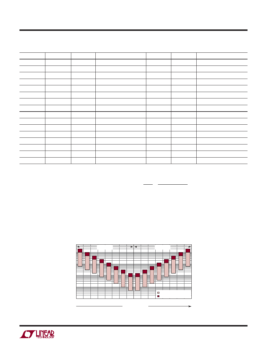
Figure 2 illustrates the information in Table 1, showing
that NDIV is symmetric around the DIVCODE midpoint.
On start-up, the DIV pin A/D converter must determine
the correct DIVCODE before the output is enabled. If VDIV
0.5V+
f OUT
(kHz)
6990 F02
1000
100
10
1
0.1
INCREASING VDIV
V+
0V
RECOMMENDED RANGE
EXTENDED RANGE
Hi-Z BIT = 0
Hi-Z BIT = 1
0
15
1
3
2
5
4
7
6
9
8
11
10
13
12
14
Figure 2. Frequency Range and Hi-Z Bit vs DIVCODE
相关PDF资料 |
PDF描述 |
|---|---|
| ELC-09D822DF | COIL CHOKE 8200UH RADIAL |
| GMC08DRAH | CONN EDGECARD 16POS R/A .100 SLD |
| 214A042-100/180-0 | BOOT MOLDED |
| ELC-09D682DF | COIL CHOKE 6800UH RADIAL |
| RCC12DRTN-S734 | CONN EDGECARD 24POS DIP .100 SLD |
相关代理商/技术参数 |
参数描述 |
|---|---|
| SCKR1J | 制造商:Vishay Dale 功能描述:S* C K U1 J E - Waffle Pack |
| SCKR1J0325 | 制造商:Vishay Dale 功能描述:S* C K U1 J R0325 E - Waffle Pack |
| SCKV100K3 | 制造商:SEMTECH 制造商全称:Semtech Corporation 功能描述:STANDARD RECOVERY HIGH VOLTAGE RECTIFIER ASSEMBLY |
| SCKV12K30 | 制造商:Semtech Corporation 功能描述:A 1PHHW 2A STD 12KV |
| SCKV12K40 | 制造商:SEMTECH 制造商全称:Semtech Corporation 功能描述:STANDARD RECOVERY HIGH VOLTAGE RECTIFIER ASSEMBLY |
发布紧急采购,3分钟左右您将得到回复。