- 您现在的位置:买卖IC网 > PDF目录11820 > SC16C554DBIA68,518 (NXP Semiconductors)IC UART QUAD SOT188-2 PDF资料下载
参数资料
| 型号: | SC16C554DBIA68,518 |
| 厂商: | NXP Semiconductors |
| 文件页数: | 52/57页 |
| 文件大小: | 0K |
| 描述: | IC UART QUAD SOT188-2 |
| 标准包装: | 250 |
| 通道数: | 4,QUART |
| FIFO's: | 16 字节 |
| 电源电压: | 2.5V,3.3V,5V |
| 带自动流量控制功能: | 是 |
| 带故障启动位检测功能: | 是 |
| 带调制解调器控制功能: | 是 |
| 带CMOS: | 是 |
| 安装类型: | 表面贴装 |
| 封装/外壳: | 68-LCC(J 形引线) |
| 供应商设备封装: | 68-PLCC |
| 包装: | 带卷 (TR) |
| 其它名称: | 935276668518 SC16C554DBIA68-T SC16C554DBIA68-T-ND |
第1页第2页第3页第4页第5页第6页第7页第8页第9页第10页第11页第12页第13页第14页第15页第16页第17页第18页第19页第20页第21页第22页第23页第24页第25页第26页第27页第28页第29页第30页第31页第32页第33页第34页第35页第36页第37页第38页第39页第40页第41页第42页第43页第44页第45页第46页第47页第48页第49页第50页第51页当前第52页第53页第54页第55页第56页第57页
2010-2012 Microchip Technology Inc.
DS41413C-page 57
PIC12(L)F1822/PIC16(L)F1823
5.2
Clock Source Types
Clock sources can be classified as external or internal.
External clock sources rely on external circuitry for the
clock source to function. Examples are: oscillator mod-
ules (EC mode), quartz crystal resonators or ceramic
resonators (LP, XT and HS modes) and Resis-
tor-Capacitor (RC) mode circuits.
Internal clock sources are contained internally within
the oscillator module. The internal oscillator block has
two internal oscillators and a dedicated Phase-Locked
Loop (HFPLL) that are used to generate three internal
system clock sources: the 16 MHz High-Frequency
Internal Oscillator (HFINTOSC), 500 kHZ (MFINTOSC)
and the 31 kHz Low-Frequency Internal Oscillator
(LFINTOSC).
The system clock can be selected between external or
internal clock sources via the System Clock Select
(SCS) bits in the OSCCON register. See Section 5.3
for additional information.
5.2.1
EXTERNAL CLOCK SOURCES
An external clock source can be used as the device
system clock by performing one of the following
actions:
Program the FOSC<2:0> bits in the Configuration
Word 1 to select an external clock source that will
be used as the default system clock upon a
device Reset.
Write the SCS<1:0> bits in the OSCCON register
to switch the system clock source to:
- Timer1 Oscillator during run-time, or
- An external clock source determined by the
value of the FOSC bits.
See Section 5.3 “Clock Switching”for more informa-
tion.
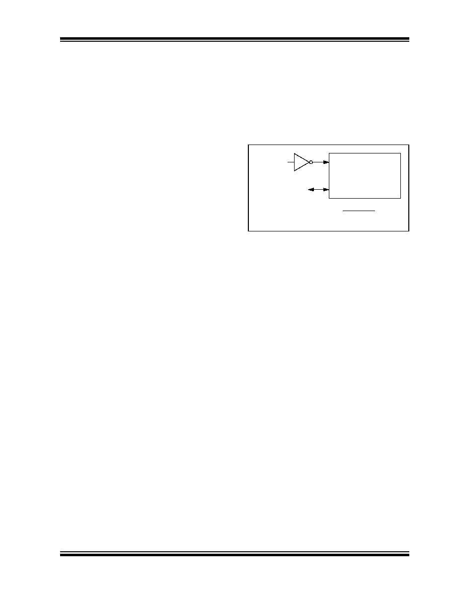
5.2.1.1
EC Mode
The External Clock (EC) mode allows an externally
generated logic level signal to be the system clock
source. When operating in this mode, an external clock
source
is
connected
to
the
OSC1
input.
OSC2/CLKOUT is available for general purpose I/O or
CLKOUT. Figure 5-2 shows the pin connections for EC
mode.
EC mode has 3 power modes to select from through
Configuration Word 1:
High-power, 4-32 MHz (FOSC = 111)
Medium power, 0.5-4 MHz (FOSC = 110)
Low-power, 0-0.5 MHz (FOSC = 101)
The Oscillator Start-up Timer (OST) is disabled when
EC mode is selected. Therefore, there is no delay in
operation after a Power-on Reset (POR) or wake-up
from Sleep. Because the PIC MCU design is fully
static, stopping the external clock input will have the
effect of halting the device while leaving all data intact.
Upon restarting the external clock, the device will
resume operation as if no time had elapsed.
FIGURE 5-2:
EXTERNAL CLOCK (EC)
MODE OPERATION
5.2.1.2
LP, XT, HS Modes
The LP, XT and HS modes support the use of quartz
crystal resonators or ceramic resonators connected to
OSC1 and OSC2 (Figure 5-3). The three modes select
a low, medium or high gain setting of the internal
inverter-amplifier to support various resonator types
and speed.
LP
Oscillator mode selects the lowest gain setting of the
internal inverter-amplifier. LP mode current consumption
is the least of the three modes. This mode is designed to
drive only 32.768 kHz tuning-fork type crystals (watch
crystals).
XT
Oscillator mode selects the intermediate gain
setting of the internal inverter-amplifier. XT mode
current consumption is the medium of the three modes.
This mode is best suited to drive resonators with a
medium drive level specification.
HS
Oscillator mode selects the highest gain setting of the
internal inverter-amplifier. HS mode current consumption
is the highest of the three modes. This mode is best
suited for resonators that require a high drive setting.
Figure 5-3 and Figure 5-4 show typical circuits for
quartz crystal and ceramic resonators, respectively.
OSC1/CLKIN
OSC2/CLKOUT
Clock from
Ext. System
PIC MCU
FOSC/4 or I/O(1)
Note
1:
Output depends upon CLKOUTEN bit of the
Configuration Word 1.
相关PDF资料 |
PDF描述 |
|---|---|
| SC28L92A1B,528 | IC UART DUAL W/FIFO 44PQFP |
| D38999/20JC98PA | CONN RCPT 10POS WALL MNT W/PINS |
| SCC2692AC1B44,551 | IC UART DUAL W/FIFO 44PQFP |
| MS3114E12-10SW | CONN RCPT 10POS JAM NUT W/SCKT |
| SCC68681E1N40,112 | IC DUART 40DIP |
相关代理商/技术参数 |
参数描述 |
|---|---|
| SC16C554DBIA68-T | 功能描述:UART 接口集成电路 16CB 2.5V-5V 4CH UART 16B FIFO RoHS:否 制造商:Texas Instruments 通道数量:2 数据速率:3 Mbps 电源电压-最大:3.6 V 电源电压-最小:2.7 V 电源电流:20 mA 最大工作温度:+ 85 C 最小工作温度:- 40 C 封装 / 箱体:LQFP-48 封装:Reel |
| SC16C554DBIB64 | 功能描述:UART 接口集成电路 16CB 2.5V-5V 4CH UART 16B FIFO RoHS:否 制造商:Texas Instruments 通道数量:2 数据速率:3 Mbps 电源电压-最大:3.6 V 电源电压-最小:2.7 V 电源电流:20 mA 最大工作温度:+ 85 C 最小工作温度:- 40 C 封装 / 箱体:LQFP-48 封装:Reel |
| SC16C554DBIB64,128 | 功能描述:UART 接口集成电路 16CB 2.5V-5V 4CH UART 16B FIFO RoHS:否 制造商:Texas Instruments 通道数量:2 数据速率:3 Mbps 电源电压-最大:3.6 V 电源电压-最小:2.7 V 电源电流:20 mA 最大工作温度:+ 85 C 最小工作温度:- 40 C 封装 / 箱体:LQFP-48 封装:Reel |
| SC16C554DBIB64,151 | 功能描述:UART 接口集成电路 4CH. UART 16B FIFO RoHS:否 制造商:Texas Instruments 通道数量:2 数据速率:3 Mbps 电源电压-最大:3.6 V 电源电压-最小:2.7 V 电源电流:20 mA 最大工作温度:+ 85 C 最小工作温度:- 40 C 封装 / 箱体:LQFP-48 封装:Reel |
| SC16C554DBIB64,157 | 功能描述:UART 接口集成电路 16CB 2.5V-5V 4CH RoHS:否 制造商:Texas Instruments 通道数量:2 数据速率:3 Mbps 电源电压-最大:3.6 V 电源电压-最小:2.7 V 电源电流:20 mA 最大工作温度:+ 85 C 最小工作温度:- 40 C 封装 / 箱体:LQFP-48 封装:Reel |
发布紧急采购,3分钟左右您将得到回复。