- 您现在的位置:买卖IC网 > PDF目录3764 > SC16C654BIA68,518 (NXP Semiconductors)IC UART QUAD W/FIFO 68-PLCC PDF资料下载
参数资料
| 型号: | SC16C654BIA68,518 |
| 厂商: | NXP Semiconductors |
| 文件页数: | 36/58页 |
| 文件大小: | 0K |
| 描述: | IC UART QUAD W/FIFO 68-PLCC |
| 产品培训模块: | Stand-Alone UARTs |
| 标准包装: | 1 |
| 特点: | 故障启动位检测 |
| 通道数: | 4,QUART |
| FIFO's: | 64 字节 |
| 电源电压: | 2.5V,3.3V,5V |
| 带自动流量控制功能: | 是 |
| 带IrDA 编码器/解码器: | 是 |
| 带故障启动位检测功能: | 是 |
| 带调制解调器控制功能: | 是 |
| 带CMOS: | 是 |
| 安装类型: | 表面贴装 |
| 封装/外壳: | 68-LCC(J 形引线) |
| 供应商设备封装: | 68-PLCC |
| 包装: | 剪切带 (CT) |
| 产品目录页面: | 828 (CN2011-ZH PDF) |
| 其它名称: | 568-2047 568-2047-ND |
第1页第2页第3页第4页第5页第6页第7页第8页第9页第10页第11页第12页第13页第14页第15页第16页第17页第18页第19页第20页第21页第22页第23页第24页第25页第26页第27页第28页第29页第30页第31页第32页第33页第34页第35页当前第36页第37页第38页第39页第40页第41页第42页第43页第44页第45页第46页第47页第48页第49页第50页第51页第52页第53页第54页第55页第56页第57页第58页
41
7674F–AVR–09/09
ATmega164P/324P/644P
8.
Power Management and Sleep Modes
8.1
Overview
Sleep modes enable the application to shut down unused modules in the MCU, thereby saving-
power. The AVR provides various sleep modes allowing the user to tailor the power
consumption to the application’s requirements.
When enabled, the Brown-out Detector (BOD) actively monitors the power supply voltage during
the sleep periods. To further save power, it is possible to disable the BOD in some sleep modes.
See “BOD Disable” on page 42 for more details.
8.2
Sleep Modes
Figure 7-1 on page 29 presents the different clock systems in the ATmega164P/324P/644P, and
their distribution. The figure is helpful in selecting an appropriate sleep mode. Table 8-1 shows
the different sleep modes, their wake up sources and BOD disable ability.
Notes:
1. Only recommended with external crystal or resonator selected as clock source.
2. If Timer/Counter2 is running in asynchronous mode.
3. For INT0, only level interrupt.
To enter any of the sleep modes, the SE bit in SMCR must be written to logic one and a SLEEP
instruction must be executed. The SM2, SM1, and SM0 bits in the SMCR Register select which
sleep mode will be activated by the SLEEP instruction. See Table 8-2 on page 46 for a
summary.
If an enabled interrupt occurs while the MCU is in a sleep mode, the MCU wakes up. The MCU
is then halted for four cycles in addition to the start-up time, executes the interrupt routine, and
resumes execution from the instruction following SLEEP. The contents of the Register File and
SRAM are unaltered when the device wakes up from sleep. If a reset occurs during sleep mode,
the MCU wakes up and executes from the Reset Vector.
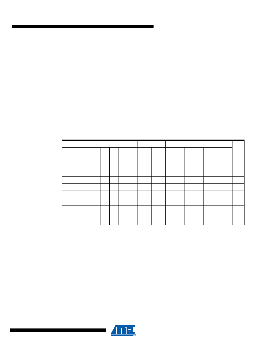
Table 8-1.
Active Clock Domains and Wake-up Sources in the Different Sleep Modes.
Active Clock Domains
Oscillators
Wake-up Sources
So
ft
wa
re
BOD
Disda
b
le
Sleep Mode
clk
CPU
clk
FLASH
clk
IO
clk
AD
C
clk
ASY
Main
Clo
c
k
So
ur
c
e
En
a
b
le
d
Time
rOsc
En
a
b
le
d
INT2:
0
and
Pi
n
C
h
a
n
g
e
TWI
Ad
d
re
ss
Matc
h
Time
r2
SP
M
/
E
EPR
O
M
R
ead
y
ADC
WD
T
Int
e
rrupt
Ot
her
I/O
Idle
X
XXXXXXX
ADCNRM
X
X(3)
XXX
Power-down
X(3)
XX
X
Power-save
X
X(3)
XX
X
Standby(1)
XX(3)
XX
X
Extended
Standby
X(2)
X(3)
XX
X
相关PDF资料 |
PDF描述 |
|---|---|
| SCC2681AC1N28,112 | IC UART 28-DIP |
| SC26C92C1B,551 | IC UART DUAL W/FIFO 44PQFP |
| SCC2692AC1A44,512 | IC UART DUAL 44-PLCC |
| SCC2692AC1N40,602 | IC UART DUAL 40-DIP |
| SCC2681AC1A44,529 | IC DUART 44-PLCC |
相关代理商/技术参数 |
参数描述 |
|---|---|
| SC16C654BIA68-S | 功能描述:UART 接口集成电路 16CB 2.5V-5V 4CH UART 64B FIFO RoHS:否 制造商:Texas Instruments 通道数量:2 数据速率:3 Mbps 电源电压-最大:3.6 V 电源电压-最小:2.7 V 电源电流:20 mA 最大工作温度:+ 85 C 最小工作温度:- 40 C 封装 / 箱体:LQFP-48 封装:Reel |
| SC16C654BIA68-T | 功能描述:UART 接口集成电路 16CB 2.5V-5V 4CH UART 64B FIFO RoHS:否 制造商:Texas Instruments 通道数量:2 数据速率:3 Mbps 电源电压-最大:3.6 V 电源电压-最小:2.7 V 电源电流:20 mA 最大工作温度:+ 85 C 最小工作温度:- 40 C 封装 / 箱体:LQFP-48 封装:Reel |
| SC16C654BIB64 | 功能描述:UART 接口集成电路 16CB 2.5V-5V 4CH UART 64B FIFO RoHS:否 制造商:Texas Instruments 通道数量:2 数据速率:3 Mbps 电源电压-最大:3.6 V 电源电压-最小:2.7 V 电源电流:20 mA 最大工作温度:+ 85 C 最小工作温度:- 40 C 封装 / 箱体:LQFP-48 封装:Reel |
| SC16C654BIB64,128 | 功能描述:UART 接口集成电路 16CB 2.5V-5V 4CH RoHS:否 制造商:Texas Instruments 通道数量:2 数据速率:3 Mbps 电源电压-最大:3.6 V 电源电压-最小:2.7 V 电源电流:20 mA 最大工作温度:+ 85 C 最小工作温度:- 40 C 封装 / 箱体:LQFP-48 封装:Reel |
| SC16C654BIB64,151 | 功能描述:UART 接口集成电路 16CB 2.5V-5V 4CH RoHS:否 制造商:Texas Instruments 通道数量:2 数据速率:3 Mbps 电源电压-最大:3.6 V 电源电压-最小:2.7 V 电源电流:20 mA 最大工作温度:+ 85 C 最小工作温度:- 40 C 封装 / 箱体:LQFP-48 封装:Reel |
发布紧急采购,3分钟左右您将得到回复。