- 您现在的位置:买卖IC网 > PDF目录11823 > SCC68681C1A44,529 (NXP Semiconductors)IC UART DUAL 44-PLCC PDF资料下载
参数资料
| 型号: | SCC68681C1A44,529 |
| 厂商: | NXP Semiconductors |
| 文件页数: | 4/29页 |
| 文件大小: | 0K |
| 描述: | IC UART DUAL 44-PLCC |
| 产品培训模块: | Stand-Alone UARTs |
| 标准包装: | 26 |
| 特点: | 故障启动位检测 |
| 通道数: | 2,DUART |
| FIFO's: | 3 位 |
| 电源电压: | 5V |
| 带自动流量控制功能: | 是 |
| 带故障启动位检测功能: | 是 |
| 带CMOS: | 是 |
| 安装类型: | 表面贴装 |
| 封装/外壳: | 44-LCC(J 形引线) |
| 供应商设备封装: | 44-PLCC |
| 包装: | 管件 |
| 其它名称: | 568-3527-5 935274497529 SCC68681C1A44-S |
第1页第2页第3页当前第4页第5页第6页第7页第8页第9页第10页第11页第12页第13页第14页第15页第16页第17页第18页第19页第20页第21页第22页第23页第24页第25页第26页第27页第28页第29页
Philips Semiconductors
Product data
SCC68681
Dual asynchronous receiver/transmitter (DUART)
2004 Apr 06
12
commands issued via the SOPR and ROPR registers. MR2[5] set to
1 caused the RTSN to be reset automatically one bit time after the
character(s) in the transmit shift register and in the THR (if any) are
completely transmitted (including the programmed number of stop
bits) if a previously issued transmitter disable is pending. This
feature can be used to automatically terminate the transmission as
follows:
1. Program the auto-reset mode: MR2[5]=1
2. Enable transmitter, if not already enabled
3. Set OPR[0] or OPR[1] to ‘1’ via SOPR and ROPR.
4. Send message
5. After the last character of the message is loaded to the THR,
disable the transmitter. (If the transmitter is underrun, a special
case exists. See note below.)
6. The last character will be transmitted and the RTSN will be reset
one bit time after the last stop bit is sent.
NOTE: The transmitter is in an underrun condition when both the
TxRDY and the TxEMT bits are set. This condition also exists
immediately after the transmitter is enabled from the disabled or
reset state. When using the above procedure with the transmitter in
the underrun condition, the issuing of the transmitter disable must be
delayed from the loading of a single, or last, character until the
TxRDY becomes active again after the character is loaded.
MR2A[4] – Channel A Clear-to-Send Control
If this bit is 0, CTSAN has no effect on the transmitter. If this bit is a
1, the transmitter checks the state of CTSAN (IP0) each time it is
ready to send a character. If IP0 is asserted (LOW), the character is
transmitted. If it is negated (HIGH), the TxDA output remains in the
marking state and the transmission is delayed until CTSAN goes
LOW. Changes in CTSAN while a character is being transmitted do
not affect the transmission of that character.
MR2A[3:0] – Channel A Stop Bit Length Select
This field programs the length of the stop bit appended to the
transmitted character. Stop bit lengths of 9/16 to 1 and 1-9/16 to 2
bits, in increments of 1/16 bit, can be programmed for character
lengths of 6, 7, and 8 bits. For a character lengths of 5 bits, 1-1/16 to
2 stop bits can be programmed in increments of 1/16 bit. The
receiver only checks for a ‘mark’ condition at the center of the first
stop bit position (one bit time after the last data bit, or after the parity
bit is enabled), in all cases.
If an external 1
× clock is used for the transmitter, MR2A[3] = 0
selects one stop bit and MR2A[3] = 1 selects two stop bits to be
transmitted.
MR1B – Channel B Mode Register 1
MR1B is accessed when the Channel B MR pointer points to MR1.
The pointer is set to MR1 by RESET or by a ‘set pointer’ command
applied via CRB. After reading or writing MR1B, the pointer will point
to MR2B.
The bit definitions for this register are identical to MR1A, except that
all control actions apply to the Channel B receiver and transmitter
and the corresponding inputs and outputs.
MR2B – Channel B Mode Register 2
MR2B is accessed when the Channel B MR pointer points to MR2,
which occurs after any access to MR1B. Accesses to MR2B do not
change the pointer.
The bit definitions for mode register are identical to the bit definitions
for MR2A, except that all control actions apply to the Channel B
receiver and transmitter and the corresponding inputs and outputs.
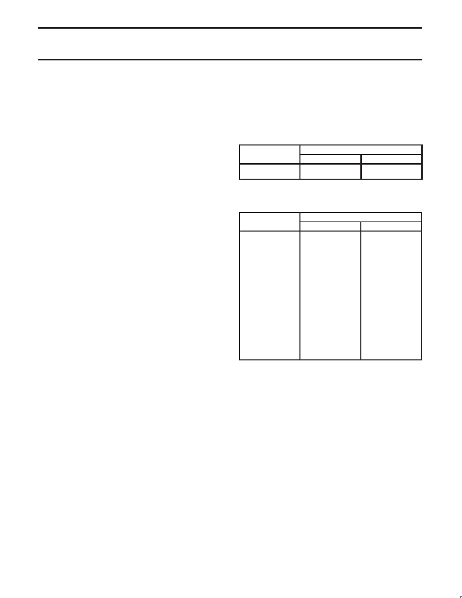
CSRA – Channel A Clock Select Register
CSRA[7:4] – Channel A Receiver Clock Select
This field selects the baud rate clock for the Channel A receiver. The
field definition is shown in Table 3.
CSRA[3:0] – Channel A Transmitter Clock Select
This field selects the baud rate clock for the Channel A transmitter.
The field definition is as shown in Table 3, except as follows:
CSRA[3:0]
Baud Rate
ACR[7] = 0
ACR[7] = 1
1110
1111
IP3–16
×
IP3–1
×
IP3–16
×
IP3–1
×
The transmitter and receiver clock is always a 16
× clock except
for 1111 selection.
Table 3.
X1 clock = 3.6864 MHz
CSRA[7:4]
Baud Rate
ACR[7] = 0
ACR[7] = 1
0000
50
75
0001
110
0010
134.5
0011
200
150
0100
300
0101
600
0110
1,200
0111
1,050
2,000
1000
2,400
1001
4,800
1010
7,200
1,800
1011
9,600
1100
38.4 k
19.2 k
1101
Timer
1110
IP4–16
×
IP4–16
×
1111
IP4–1
×
IP4–1
×
See Table 6 for other rates to 115.2 k baud.
相关PDF资料 |
PDF描述 |
|---|---|
| VI-B2Z-IY | CONVERTER MOD DC/DC 2V 20W |
| VE-J5J-IW-F4 | CONVERTER MOD DC/DC 36V 100W |
| VE-J5J-IW-F3 | CONVERTER MOD DC/DC 36V 100W |
| VI-B2X-IY | CONVERTER MOD DC/DC 5.2V 50W |
| VE-J5J-IW-F2 | CONVERTER MOD DC/DC 36V 100W |
相关代理商/技术参数 |
参数描述 |
|---|---|
| SCC68681C1A44-T | 功能描述:UART 接口集成电路 RPLCMNT FOR SCN68681 RoHS:否 制造商:Texas Instruments 通道数量:2 数据速率:3 Mbps 电源电压-最大:3.6 V 电源电压-最小:2.7 V 电源电流:20 mA 最大工作温度:+ 85 C 最小工作温度:- 40 C 封装 / 箱体:LQFP-48 封装:Reel |
| SCC68681C1N40 | 制造商:PHILIPS 制造商全称:NXP Semiconductors 功能描述:Dual asynchronous receiver/transmitter |
| SCC68681C1N40,112 | 功能描述:UART 接口集成电路 2CH.UART RoHS:否 制造商:Texas Instruments 通道数量:2 数据速率:3 Mbps 电源电压-最大:3.6 V 电源电压-最小:2.7 V 电源电流:20 mA 最大工作温度:+ 85 C 最小工作温度:- 40 C 封装 / 箱体:LQFP-48 封装:Reel |
| SCC68681C1N40112 | 制造商:Rochester Electronics LLC 功能描述: 制造商:NXP 功能描述: 制造商:NXP Semiconductors 功能描述: |
| SCC68681E1A44 | 功能描述:UART 接口集成电路 RPLCMNT FOR SCN68681 RoHS:否 制造商:Texas Instruments 通道数量:2 数据速率:3 Mbps 电源电压-最大:3.6 V 电源电压-最小:2.7 V 电源电流:20 mA 最大工作温度:+ 85 C 最小工作温度:- 40 C 封装 / 箱体:LQFP-48 封装:Reel |
发布紧急采购,3分钟左右您将得到回复。