参数资料
| 型号: | SCC68692C1A44,512 |
| 厂商: | NXP Semiconductors |
| 文件页数: | 9/28页 |
| 文件大小: | 0K |
| 描述: | IC UART DUAL 44-PLCC |
| 产品培训模块: | Stand-Alone UARTs |
| 标准包装: | 26 |
| 特点: | 故障启动位检测 |
| 通道数: | 2,DUART |
| FIFO's: | 3 位 |
| 电源电压: | 5V |
| 带并行端口: | 是 |
| 带自动流量控制功能: | 是 |
| 带故障启动位检测功能: | 是 |
| 带CMOS: | 是 |
| 安装类型: | 表面贴装 |
| 封装/外壳: | 44-LCC(J 形引线) |
| 供应商设备封装: | 44-PLCC |
| 包装: | 管件 |
| 产品目录页面: | 828 (CN2011-ZH PDF) |
| 其它名称: | 568-1121-5 933977630512 SCC68692C1A44 |
第1页第2页第3页第4页第5页第6页第7页第8页当前第9页第10页第11页第12页第13页第14页第15页第16页第17页第18页第19页第20页第21页第22页第23页第24页第25页第26页第27页第28页
Philips Semiconductors
Product data
SCC68692
Dual asynchronous receiver/transmitter (DUART)
2004 Mar 03
17
OPCR[1:0] – OP2 Output Select
This field programs the OP2 output to provide one of the following:
00 The complement of OPR[2].
01 The 16X clock for the Channel A transmitter. This is the clock
selected by CSRA[3:0], and will be a 1X clock if CSRA[3:0] =
1111.
10 The 1X clock for the Channel A transmitter, which is the clock
that shifts the transmitted data. If data is not being transmitted, a
free running 1X clock is output.
11 The 1X clock for the Channel A receiver, which is the clock that
samples the received data. If data is not being received, a free
running 1X clock is output.
ACR – Auxiliary Control Register
ACR[7] – Baud Rate Generator Set Select
This bit selects one of two sets of baud rates to be generated by the
BRG.
Set 1:
50, 110, 134.5, 200, 300, 600, 1.05k, 1.2k, 2.4k, 4.8k, 7.2k, 9.6k, and 38.4k baud.
Set 2:
75, 110, 134.5, 150, 300, 600, 1.2k, 1.8k, 2.0k, 2.4k, 4.8k, 9.6k, and 19.2k baud.
Table 4.
Bit Rate Generator Characteristics
Crystal or Clock = 3.6864MHz
BAUD RATE
ACTUAL 16X CLOCK (kHz)
ERROR (%)
50
0.8
0
75
1.2
0
110
1.759
–0.069
134.5
2.153
0.059
150
2.4
0
200
3.2
0
300
4.8
0
600
9.6
0
1050
16.756
–0.260
1200
19.2
0
1800
28.8
0
2000
32.056
0.175
2400
38.4
0
4800
76.8
0
7200
115.2
0
9600
153.6
0
14.4K
230.4
0
19.2K
307.2
0
28.8K
460.8
0
38.4K
614.4
0
57.6K
921.2
0
115.2K
1,843.2
0
NOTE: Duty cycle of 16X clock is 50%
±1%.
Asynchronous UART communications can tolerate frequency error
of 4.1% to 6.7% in a “clean” communications channel. The percent
of error changes as the character length changes. The above
percentages range from 5 bits not parity to 8 bits with parity and one
stop bit. The error with 8 bits no parity and one stop bit is 4.6%. If a
stop bit length of 9/16 is used, the error tolerance will approach 0
due to a variable error of up to 1/16 bit time in receiver clock phase
alignment to the start bit.
The selected set of rates is available for use by the Channel A and
B receivers and transmitters as described in CSRA and CSRB.
Baud rate generator characteristics are given in Table 4.
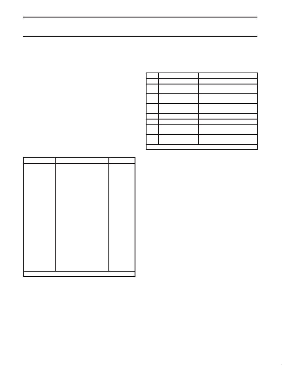
ACR[6:4] – Counter/Timer Mode And Clock Source Select
This field selects the operating mode of the counter/timer and its
clock source as shown in Table 5.
Table 5.
ACR [6:4] Field Definition
[6:4]
MODE
CLOCK SOURCE
000
Counter
External (IP2)
001
Counter
TxCA – 1x clock of Channel A
transmitter
010
Counter
TxCB – 1x clock of Channel B
transmitter
011
Counter
Crystal or external (x1/CLK)
divided by 16
100
Timer (square wave)
External (IP2)
101
Timer (square wave)
External (IP2) divided by 16
110
Timer (square wave)
Crystal or external clock
(X1/CLK)
111
Timer (square wave)
Crystal or IP2 clock (X1/CLK)
divided by 16
NOTE: Timer mode generates a squarewave.
ACR[3:0] – IP3, IP2, IP1, IP0 Change-of-State Interrupt Enable
This field selects which bits of the input port change register (IPCR)
cause the input change bit in the interrupt status register (ISR[7]) to
be set. If a bit is in the ‘on’ state the setting of the corresponding bit
in the IPCR will also result in the setting of ISR[7], which results in
the generation of an interrupt output if IMR[7] = 1. If a bit is in the
‘off’ state, the setting of that bit in the IPCR has no effect on ISR[7].
IPCR – Input Port Change Register
IPCR[7:4] – IP3, IP2, IP1, IP0 Change-of-State
These bits are set when a change-of-state, as defined in the input
port section of this data sheet, occurs at the respective input pins.
They are cleared when the IPCR is read by the CPU. A read of the
IPCR also clears ISR[7], the input change bit in the interrupt status
register. The setting of these bits can be programmed to generate
an interrupt to the CPU.
IPCR[3:0] – IP3, IP2, IP1, IP0 Change-of-State
These bits provide the current state of the respective inputs. The
information is unlatched and reflects the state of the input pins at the
time the IPCR is read.
ISR – Interrupt Status Register
This register provides the status of all potential interrupt sources.
The contents of this register are masked by the Interrupt Mask
Register (IMR). If a bit in the ISR is a ‘1’ and the corresponding bit in
the IMR is also a ‘1’, the INTRN output will be asserted (LOW). If the
corresponding bit in the IMR is a zero, the state of the bit in the ISR
has no effect on the INTRN output. Note that the IMR does not mask
the reading of the ISR – the true status will be provided regardless
of the contents of the IMR. The contents of this register are
initialized to H‘00’ when the DUART is reset.
ISR[7] – Input Port Change Status
This bit is a ‘1’ when a change-of-state has occurred at the IP0, IP1,
IP2, or IP3 inputs and that event has been selected to cause an
interrupt by the programming of ACR[3:0]. The bit is cleared when
the CPU reads the IPCR.
相关PDF资料 |
PDF描述 |
|---|---|
| SCC68692C1A44,518 | IC DUART 44PLCC |
| ATMEGA164PA-AUR | MCU AVR 16KB FLASH 20MHZ 44TQFP |
| SC16C654BIB64,151 | IC UART QUAD W/FIFO 64-LQFP |
| SC16C654DBIB64,151 | IC UART QUAD W/FIFO 64-LQFP |
| ATMEGA164PA-MUR | MCU AVR 16KB FLASH 20MHZ 44QFN |
相关代理商/技术参数 |
参数描述 |
|---|---|
| SCC68692C1A44-S | 功能描述:UART 接口集成电路 5V IND. UART 2 CH. MOT INTERF. RoHS:否 制造商:Texas Instruments 通道数量:2 数据速率:3 Mbps 电源电压-最大:3.6 V 电源电压-最小:2.7 V 电源电流:20 mA 最大工作温度:+ 85 C 最小工作温度:- 40 C 封装 / 箱体:LQFP-48 封装:Reel |
| SCC68692C1A44-T | 制造商:NXP Semiconductors 功能描述:UART 2-CH 5V 44-Pin PLCC |
| SCC68692C1F40 | 制造商:PHILIPS 制造商全称:NXP Semiconductors 功能描述:Dual asynchronous receiver/transmitter DUART |
| SCC68692C1N40 | 制造商:NXP Semiconductors 功能描述:IC CMOS DUAL UART 68692 DIP40 |
| SCC68692C1N40,602 | 功能描述:UART 接口集成电路 5V IND. UART 2 CH. MOT INTERF. RoHS:否 制造商:Texas Instruments 通道数量:2 数据速率:3 Mbps 电源电压-最大:3.6 V 电源电压-最小:2.7 V 电源电流:20 mA 最大工作温度:+ 85 C 最小工作温度:- 40 C 封装 / 箱体:LQFP-48 封装:Reel |
发布紧急采购,3分钟左右您将得到回复。