- 您现在的位置:买卖IC网 > PDF目录378690 > SF86 (DC Components Co., Ltd.) TECHNICAL SPECIFICATIONS OF SUPER FAST RECTIFIER PDF资料下载
参数资料
| 型号: | SF86 |
| 厂商: | DC Components Co., Ltd. |
| 英文描述: | TECHNICAL SPECIFICATIONS OF SUPER FAST RECTIFIER |
| 中文描述: | 技术规格超快速整流 |
| 文件页数: | 1/2页 |
| 文件大小: | 39K |
| 代理商: | SF86 |
8.0 AMP SUPER FAST RECTIFIERS
MAXIMUM RATINGS AND ELECTRICAL CHARACTERISTICS
Rating 25 C ambient temperature uniess otherwies specified.
Single phase half wave, 60Hz, resistive or inductive load.
For capacitive load, derate current by 20%.
TYPE NUMBER
Maximum Recurrent Peak Reverse Voltage
Maximum RMS Voltage
Maximum DC Blocking Voltage
Maximum Average Forward Rectified Current
.375"(9.5mm) Lead Length at Tc=100 C
Peak Forward Surge Current, 8.3 ms single half sine-wave
superimposed on rated load (JEDEC method)
Maximum Instantaneous Forward Voltage at 8.0A
Maximum DC Reverse Current Tc=25 C
at Rated DC Blocking Voltage Tc=100 C
Maximum Reverse Recovery Time (Note 1)
Typical Junction Capacitance (Note 2)
Operating and Storage Temperature Range T
J
, T
STG
8.0
125
10
500
50
-65 +150
A
A
V
m
A
m
A
nS
pF
C
NOTES:
1. Reverse Recovery Time test condition: IF=0.5A, IR=1.0A, IRR=0.25A
2. Measured at 1MHz and applied reverse voltage of 4.0V D.C.
S F81
T HRU
S F87
35
50
FEATURES
MECHANICAL DATA
* Case: Molded plastic
* Epoxy: UL 94V-0 rate flame retardant
* Lead: Lead solderable per MIL-STD-202,
method 208 guranteed
* Polarity: As Marked
* Mounting position: Any
* Weight: 2.24 grams
* Low forward voltage drop
* High current capability
* High reliability
* High surge current capability
* Good for switching mode application
VOLTAGE RANGE
50 to 600 Volts
CURRENT
8.0 Amperes
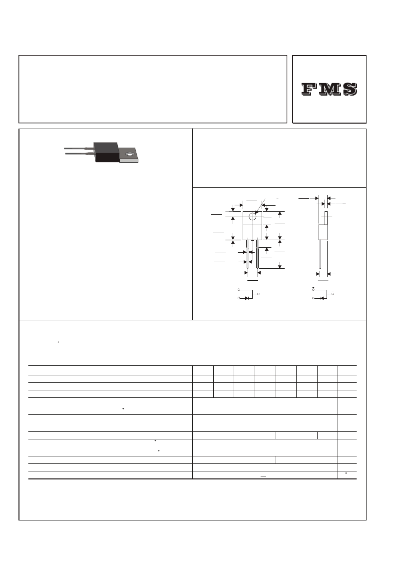
TO-220A
3.8 +.2
HOLE THRU
Dimensions in inches and (millimeters)
.412
(10.5)
MAX.
.248
(6.3)
.040
(1.0)
MAX.
.180
(4.6)
.050
(1.27)
.120
(3.05)
.158
(4.0)
MAX.
.595
(15.1)
MAX.
.550
(14.0)
MIN.
.200
(5.08)
.051
(1.3)
.040
(1.0)
.108
(2.75)
MAX.
MAX.
+
+
+
PIN 1
PIN 1
PIN 2
PIN 2
CASE
CASE
Case Positive
Case Negative
Suffix "R"
SF81 SF82
SF83
SF84
SF85
SF86
SF87 UNITS
50 100 150 200 300 400 600 V
35 70 105 140 210 280 420
50 100 150 200 300 400 600 V
V
0.95
1.30
1.50
相关PDF资料 |
PDF描述 |
|---|---|
| SFE1A | Superfast Switching Surface Mount Si-Rectifiers |
| SFE1B | Superfast Switching Surface Mount Si-Rectifiers |
| SFE1D | Superfast Switching Surface Mount Si-Rectifiers |
| SFE1G | Superfast Switching Surface Mount Si-Rectifiers |
| SFE1J | Superfast Switching Surface Mount Si-Rectifiers |
相关代理商/技术参数 |
参数描述 |
|---|---|
| SF860F | 制造商:LUGUANG 制造商全称:Shenzhen Luguang Electronic Technology Co., Ltd 功能描述:Super Fast Rectifiers |
| SF868M35 | 制造商:VANLONG 制造商全称:VANLONG 功能描述:868.35 MHz SAW Filter |
| SF868M35B | 制造商:VANLONG 制造商全称:VANLONG 功能描述:868.35 MHz SAW Filter |
| SF868M35C | 制造商:VANLONG 制造商全称:VANLONG 功能描述:868.35 MHz SAW Filter |
| SF869C | 制造商:VANLONG 制造商全称:VANLONG 功能描述:869.00 MHz SAW Filter |
发布紧急采购,3分钟左右您将得到回复。