- 您现在的位置:买卖IC网 > PDF目录66214 > SFH612A (VISHAY INTERTECHNOLOGY INC) 1 CHANNEL DARLINGTON OUTPUT OPTOCOUPLER PDF资料下载
参数资料
| 型号: | SFH612A |
| 厂商: | VISHAY INTERTECHNOLOGY INC |
| 元件分类: | 光电耦合器 |
| 英文描述: | 1 CHANNEL DARLINGTON OUTPUT OPTOCOUPLER |
| 封装: | PLASTIC, DIP-4 |
| 文件页数: | 1/3页 |
| 文件大小: | 396K |
| 代理商: | SFH612A |
Document Number: 83667
www.vishay.com
Revision 17-August-01
2–231
FEATURES
High Current Transfer Ratio
SFH612A=200% (min.)
SFH655A=600% (min.)
High Isolation Test Voltage 5300 VRMS
Standard Plastic DIP-4 Package
Underwriters Lab File #E52744
DESCRIPTION
The SFH612A and SFH655A are optically coupled
isolators with a Gallium Arsenide infrared LED and a
silicon photodarlington detector. Switching can be
achieved while maintaining a high degree of isola-
tion between driving and load circuits. These opto-
couplers can be used to replace reed and mercury
relays with advantages of long life, high speed
switching and elimination of magnetic elds.
Maximum Ratings TA=25°C
Emitter
Peak Reverse Voltage....................................... 6.0 V
Continuous Forward Current ........................ 60 mA
Surge Forward Current (tp≤10 s) ....................2.5 A
Derate Linearly from 25
°C.....................1.33 mW/°C
Power Dissipation at 25
°C ......................... 100 mW
Detector
Collector–Emitter Breakdown Voltage
BVCEO ........................................................... 55 V
Emitter–Collector Breakdown Voltage
BVECO ........................................................... 6.0 V
Collector (load) Current ................................125 mA
Derate Linearly from 25
°C.....................2.00 mW/°C
Power Dissipation at 25
°C ......................... 150 mW
Package
Derate Linearly from 25
°C.....................3.33 mW/°C
Total Power Dissipation at 25
°C ................ 250 mW
Isolation Test Voltage between input and
output, climate acc. to IEC 60068-1:1988
(t=1.0 s)................................................5300 VRMS
Creepage Distance
............................................ ≥7.0 mm
Clearance
............................................................. ≥7.0 mm
Comparative Tracking Index acc. to
DIN IEC 112/VDE 0303, part 1:06-84] .........
≥175
Isolation Resistance VIO=500 V/25°C ............ ≥10
12
Isolation Resistance VIO=500 V/100°C .......... ≥10
11
Storage Temperature Range.......... –55
°C to +150°C
Operating Temperature Range ...... –55
°C to +100°C
Soldering Temperature
(max. 10 s, dip soldering:
distance to seating plane
≥1.5 mm)............ 260
°C
Electrical Characteristics TA=25°C unless otherwise specied
Parameter
Sym.
Min. Typ. Max. Unit Condition
Emitter
Forward Voltage
VF
—
1.15 1.5
V
IF=10 mA
Reverse Current
IR
—
0.02 10
A VR=6.0 V
Capacitance
CO
—14
—
pF
VR=0 V, f=1.0 MHz
Detector
Breakdown Voltage
Collector–Emitter
BVCEO 55
—
V
ICE=100 A
Breakdown Voltage
Emitter–Collector
BVECO 6.0
—
V
IEC=10 A
Collector–Emitter
Dark Current
ICEO
—
12
400
nA
VCE=40 V
Capacitance
Collector–Emitter
CCE
—
13.5 —
pF
VCE=0 V, f=1.0 MHz
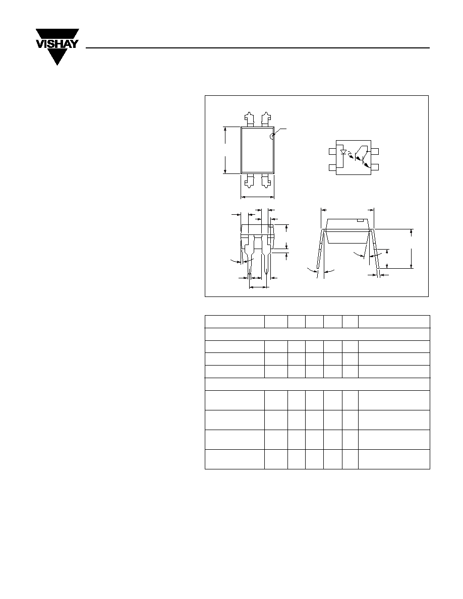
.255 (6.48)
.268 (6.81)
1
2
4
3
.179 (4.55)
.190 (4.83)
pin one ID
.030 (.76)
.045 (1.14)
4
°
typ.
0.100 (2.54)
.130 (3.30)
.150 (3.81)
.020 (.508 )
.035 (.89)
10
°
3
°–9°
.018 (.46)
.022 (.56)
.008 (.20)
.012 (.30)
.031 (.79) typ.
.050 (1.27) typ.
.300 (7.62) typ.
.110 (2.79)
.130 (3.30)
.230 (5.84)
.250 (6.35)
.050 (1.27)
Dimensions in inches (mm)
1
2
3
Collector
Emitter
Anode
Cathode
4
SFH612A/655A
Photodarlington Optocoupler
相关PDF资料 |
PDF描述 |
|---|---|
| SFH655A | 1 CHANNEL DARLINGTON OUTPUT OPTOCOUPLER |
| SFH6156-2SM | 1 CHANNEL TRANSISTOR OUTPUT OPTOCOUPLER |
| SFH615AGR | 1 CHANNEL TRANSISTOR OUTPUT OPTOCOUPLER |
| SFH615AGB | 1 CHANNEL TRANSISTOR OUTPUT OPTOCOUPLER |
| SFH615A | 1 CHANNEL TRANSISTOR OUTPUT OPTOCOUPLER |
相关代理商/技术参数 |
参数描述 |
|---|---|
| SFH612A | 制造商:Vishay Semiconductors 功能描述:OPTOCOUPLER |
| SFH6135 | 功能描述:高速光耦合器 1Mbd Open Collector Single Channel RoHS:否 制造商:Avago Technologies 电流传递比: 最大波特率: 最大正向二极管电压:1.75 V 最大反向二极管电压:5 V 最大功率耗散:40 mW 最大工作温度:+125 C 最小工作温度:- 40 C 封装 / 箱体:SOIC-5 封装:Tube |
| SFH6135-X001 | 功能描述:高速光耦合器 1Mbd High-Speed Trans Out CTR>5-7% RoHS:否 制造商:Avago Technologies 电流传递比: 最大波特率: 最大正向二极管电压:1.75 V 最大反向二极管电压:5 V 最大功率耗散:40 mW 最大工作温度:+125 C 最小工作温度:- 40 C 封装 / 箱体:SOIC-5 封装:Tube |
| SFH6135-X006 | 功能描述:高速光耦合器 1Mbd High-Speed Trans Out CTR>5-7% RoHS:否 制造商:Avago Technologies 电流传递比: 最大波特率: 最大正向二极管电压:1.75 V 最大反向二极管电压:5 V 最大功率耗散:40 mW 最大工作温度:+125 C 最小工作温度:- 40 C 封装 / 箱体:SOIC-5 封装:Tube |
| SFH6135-X007 | 功能描述:高速光耦合器 1Mbd High-Speed Trans Out CTR>5-7% RoHS:否 制造商:Avago Technologies 电流传递比: 最大波特率: 最大正向二极管电压:1.75 V 最大反向二极管电压:5 V 最大功率耗散:40 mW 最大工作温度:+125 C 最小工作温度:- 40 C 封装 / 箱体:SOIC-5 封装:Tube |
发布紧急采购,3分钟左右您将得到回复。