- 您现在的位置:买卖IC网 > PDF目录85346 > SFH6316T-X001 (VISHAY SEMICONDUCTORS) 1 CHANNEL LOGIC OUTPUT OPTOCOUPLER, 1 Mbps PDF资料下载
参数资料
| 型号: | SFH6316T-X001 |
| 厂商: | VISHAY SEMICONDUCTORS |
| 元件分类: | 光电耦合器 |
| 英文描述: | 1 CHANNEL LOGIC OUTPUT OPTOCOUPLER, 1 Mbps |
| 封装: | ROHS COMPLIANT, SOIC-8 |
| 文件页数: | 3/7页 |
| 文件大小: | 130K |
| 代理商: | SFH6316T-X001 |
Document Number: 83677
For technical questions, contact: optocoupleranswers@vishay.com
www.vishay.com
Rev. 2.1, 19-Oct-10
3
SFH6315T, SFH6316T, SFH6343T
High Speed Optocoupler, 1 MBd,
Transistor Output
Vishay Semiconductors
Notes
Minimum and maximum values are testing requirements. Typical values are characteristics of the device and are the result of engineering
evaluation. Typical values are for information only and are not part of the testing requirements.
(1) A 0.1 μF bypass capacitor connected between pins 5 and 8 is recommended.
Note
Current transfer ratio in percent equals the ratio of output collector current (IO) to the forward LED input current (IF) times 100.
A 0.1 μF bypass capacitor connected between pins 5 and 8 is recommended.
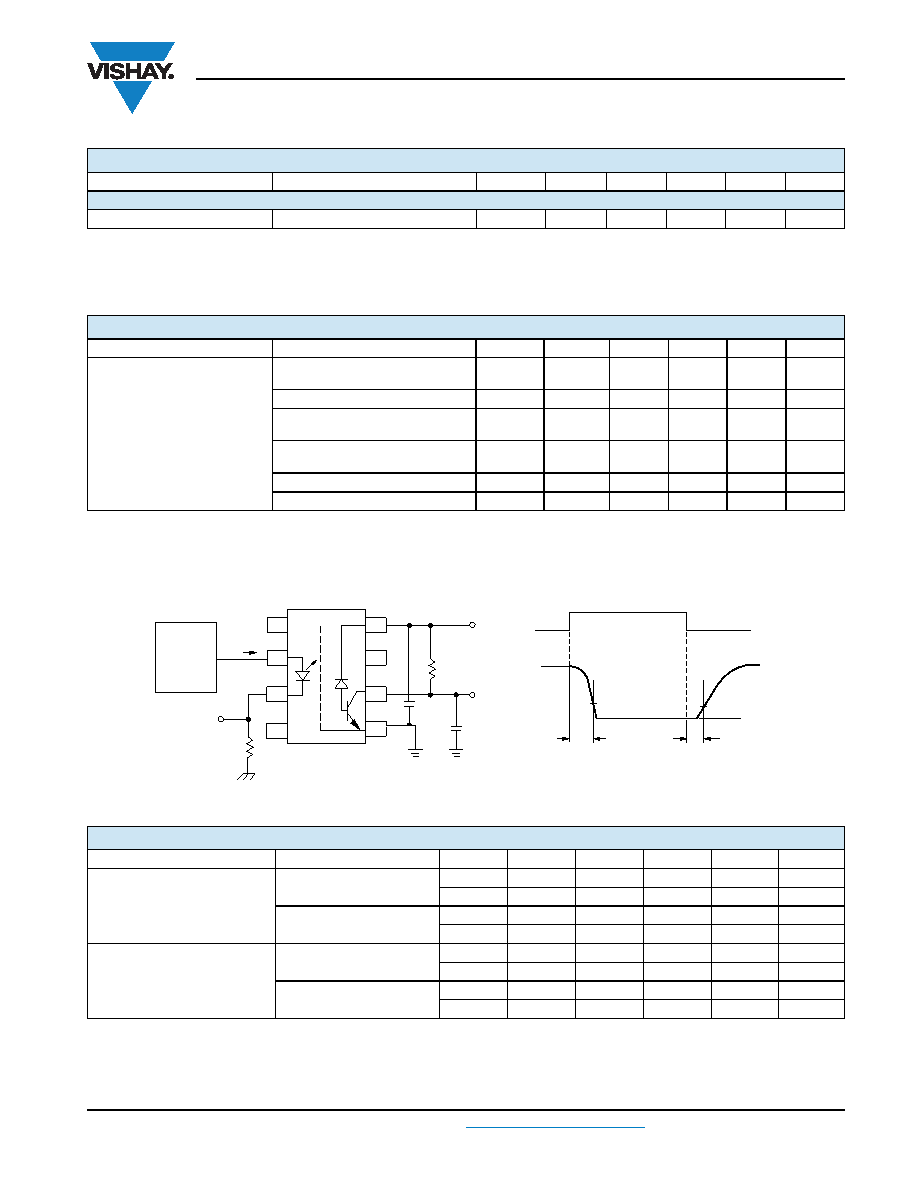
Fig. 1 - Test Circuit for Switching Times
Notes
Over recommended temperature (Tamb = 0 °C to 70 °C ), VCC = 5 V, IF = 16 mA unless otherwise specified.
The 1.9 kW load represents 1 TTL unit load of 1.6 mA and the 5.6 kW pull-up resistor.
The 4.1 kW load represents 1 LSTTL unit load of 0.36 mA and the 6.1 kW pull-up resistor.
(1) Tamb = 25 °C, unless otherwise specified.
COUPLER
Capacitance (input to output) (1)
f = 1 MHz
CIO
0.4
pF
CURRENT TRANSFER RATIO
PARAMETER
TEST CONDITION
PART
SYMBOL
MIN.
TYP.
MAX.
UNIT
Current transfer ratio
VO = 0.4 V, IF = 16 mA, VCC = 4.5 V,
25 °C
SFH6315T
CTR
7
16
50
%
VO = 0.5 V, IF = 16 mA, VCC = 4.5 V
SFH6315T
CTR
5
17
%
VO = 0.4 V, IF = 16 mA, VCC = 4.5 V,
25 °C
SFH6316T
CTR
19
35
50
%
VO = 0.4 V, IF = 16 mA, VCC = 4.5 V,
25 °C
SFH6343T
CTR
19
35
50
%
VO = 0.5 V, IF = 16 mA, VCC = 4.5 V
SFH6343T
CTR
15
36
%
VO = 0.5 V, IF = 16 mA, VCC = 4.5 V
SFH6316T
CTR
15
36
%
ELECTRICAL CHARACTERISTICS (Tamb = 25 °C, unless otherwise specified)
PARAMETER
TEST CONDITION
PART
SYMBOL
MIN.
TYP.
MAX.
UNIT
SWITCHING CHARACTERISTICS
PARAMETER
TEST CONDITION
PART
SYMBOL
MIN.
TYP.
MAX.
UNIT
Propagation delay time to logic
low at output (see fig. 1)
RL = 4.1 K
Ω
SFH6315T
tPHL (1)
0.5
1.5
μs
SFH6315T
tPHL
0.5
2
μs
RL = 1.9 K
Ω
SFH6316T
tPHL
0.25
0.8
μs
SFH6343T
tPHL
0.25
1
μs
Propagation delay time to logic
high at output (see fig. 1)
RL = 4.1 K
Ω
SFH6315T
tPLH (1)
0.5
1.5
μs
SFH6315T
tPLH
0.5
2
μs
RL = 1.9 K
Ω
SFH6316T
tPLH
0.5
0.8
μs
SFH6343T
tPLH
0.5
1
μs
isfh6315t_01
5 V
VO
tPLH
tPHL
VOL
0
IF
1.5 V
1
2
3
4
8
7
6
5
Pulse
generator
ZO = 50 Ω
tr = 5 ns
IF = monitor
10 % duty cycle
1/f < 100 s
IF
RL
V
O
CL = 15 pF
0.1 F
+ 5 V
R M
相关PDF资料 |
PDF描述 |
|---|---|
| SR505D | SINGLE COLOR LED, BRIGHT RED, 2.7 mm |
| SLR-343VC3FP | T-1 SINGLE COLOR LED, RED, 3.1 mm |
| SFH617A-3 | 1 CHANNEL TRANSISTOR OUTPUT OPTOCOUPLER |
| S-879-T5F | 3.175 mm SLOT WIDTH, 1 CHANNEL SLOTTED OPTICAL SWITCH TRANSISTOR OUTPUT |
| S-881-L51 | 3.175 mm SLOT WIDTH, 1 CHANNEL SLOTTED OPTICAL SWITCH TRANSISTOR OUTPUT |
相关代理商/技术参数 |
参数描述 |
|---|---|
| SFH6318 | 制造商:INFINEON 制造商全称:Infineon Technologies AG 功能描述:LOW CURRENT, HIGH GAIN OPTOCOUPLER |
| SFH6318T | 功能描述:高速光耦合器 100kbd Low Input Current High Gain RoHS:否 制造商:Avago Technologies 电流传递比: 最大波特率: 最大正向二极管电压:1.75 V 最大反向二极管电压:5 V 最大功率耗散:40 mW 最大工作温度:+125 C 最小工作温度:- 40 C 封装 / 箱体:SOIC-5 封装:Tube |
| SFH6318T | 制造商:Vishay Semiconductors 功能描述:Optocoupler |
| SFH6319 | 制造商:INFINEON 制造商全称:Infineon Technologies AG 功能描述:LOW CURRENT, HIGH GAIN OPTOCOUPLER |
| SFH6319 | 制造商:Vishay Intertechnologies 功能描述:OPTOCOUPLER SMD TRANSISTOR O/P |
发布紧急采购,3分钟左右您将得到回复。