- 您现在的位置:买卖IC网 > PDF目录40169 > SHD3163B (SENSITRON SEMICONDUCTOR) 8 A, SILICON, RECTIFIER DIODE PDF资料下载
参数资料
| 型号: | SHD3163B |
| 厂商: | SENSITRON SEMICONDUCTOR |
| 元件分类: | 整流器 |
| 英文描述: | 8 A, SILICON, RECTIFIER DIODE |
| 封装: | HERMETIC, SHD-1B, 2 PIN |
| 文件页数: | 3/12页 |
| 文件大小: | 131K |
| 代理商: | SHD3163B |
221 West Industry Court Deer Park, NY 11729-4681 Phone (631) 586-7600 Fax (631) 242-9798
World Wide Web Site - http://www.sensitron.com E-Mail Address - sales@sensitron.com
TECHNICAL DATA
DATA SHEET 655, REV. -
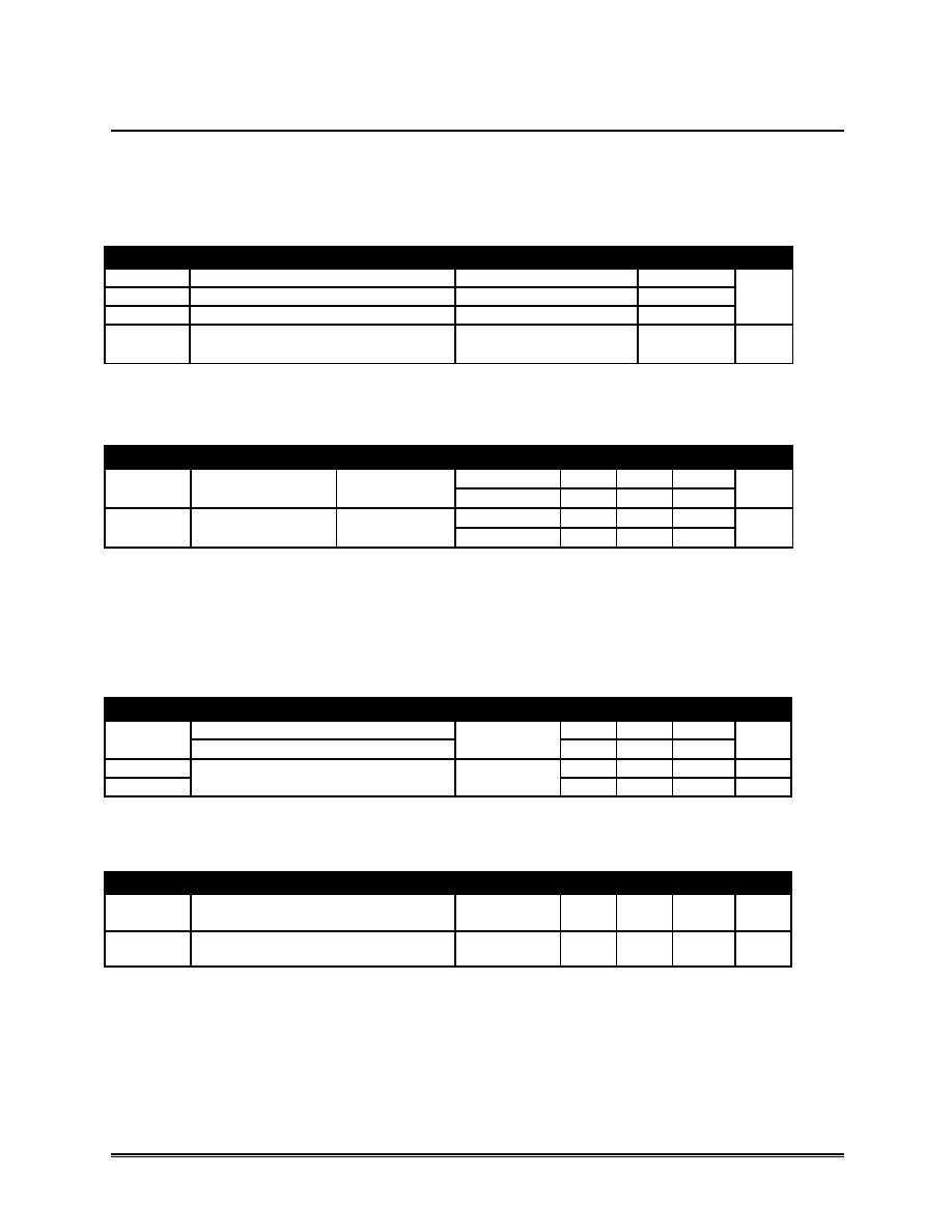
THERMAL AND POWER DATA
Symbol Parameter
Test Conditions
Value
Unit
Rth (j-c)
Junction to case thermal resistance
Per Diode
5.0
Rth (c)
Coupling
0.2
Rth (j-c)
Junction to case thermal resistance
Total
2.6
°C/W
P1
Conduction power dissipation for
both diodes
IF(AV) = 8A δ = 0.5
TC = 80°C
27
W
STATIC ELECTRICAL CHARACTERISTICS (for both diodes)
Symbol
Parameter
Test Conditions
Min.
Typ. Max.
Unit
Tj = 25
°C
-
10
IR *
Reverse leakage
current
VR = VRRM
Tj = 125
°C
-
15
100
A
Tj = 25
°C
-
3.6
VF **
Forward voltage
drop
IF = 8A
Tj = 125
°C
-
2.1
2.6
V
Pulse test: * tp = 5 ms,
δ < 2%
** tp = 380
s, δ < 2%
To evaluate the maximum conduction losses use the following equation:
P = 1.8 x IF(AV) + 0.1 IF
2
(RMS)
RECOVERY CHARACTERISTICS
Symbol
Test Conditions
Min.
Typ. Max.
Unit
IF = 0.5A
Irr = 0.25A
IR = 1A
-
13
-
trr
IF = 1A
dlF/dt = -50A/s VR = 30V
Tj = 25
°C
-
30
ns
IRM
-
4.0
5.5
A
Sfactor
VR = 400V IF = 8A dlF = -200 A/s
Tj = 125
°C
-
0.4
-
TURN-ON SWITCHING CHARACTERISTICS
Symbol
Test Conditions
Min.
Typ. Max.
Unit
tfr
IF = 8A
dlF/dt = 100A/s,
Measured at 1.1 x VF max
Tj = 25
°C
-
200
ns
VFP
IF = 8A
dlF/dt = 100A/s
Tj = 25
°C
-
7.0
V
APPLICATION DATA:
The Free Wheeling Switch is especially designed to provide the lowest overall power losses in any “Free
Wheel Mode” application considering both diode and companion transistor, thus optimizing overall
performance in the end application.
SHD326213
相关PDF资料 |
PDF描述 |
|---|---|
| SHD3157 | 70 A, SILICON, RECTIFIER DIODE |
| SHD3251N | 30 A, SILICON, RECTIFIER DIODE, TO-254AA |
| SHD3153A | 30 A, SILICON, RECTIFIER DIODE |
| SSM65HE | 6 A, SILICON, RECTIFIER DIODE |
| SHD3185PA | 100 A, SILICON, RECTIFIER DIODE |
相关代理商/技术参数 |
参数描述 |
|---|---|
| SHD325311 | 制造商:SENSITRON 制造商全称:Sensitron 功能描述:HERMETIC ULTRAFAST RECTIFIER |
| SHD325311D | 制造商:SENSITRON 制造商全称:Sensitron 功能描述:HERMETIC ULTRAFAST RECTIFIER |
| SHD325311N | 制造商:SENSITRON 制造商全称:Sensitron 功能描述:HERMETIC ULTRAFAST RECTIFIER |
| SHD325311P | 制造商:SENSITRON 制造商全称:Sensitron 功能描述:HERMETIC ULTRAFAST RECTIFIER |
| SHD325314N | 制造商:Sensitron Semiconductors 功能描述: |
发布紧急采购,3分钟左右您将得到回复。