- 您现在的位置:买卖IC网 > PDF目录10910 > SI3018-F-FS-R (Silicon Laboratories Inc)IC ISOMODEM LINE-SIDE DAA 16SOIC PDF资料下载
参数资料
| 型号: | SI3018-F-FS-R |
| 厂商: | Silicon Laboratories Inc |
| 文件页数: | 20/94页 |
| 文件大小: | 0K |
| 描述: | IC ISOMODEM LINE-SIDE DAA 16SOIC |
| 标准包装: | 2,500 |
| 系列: | ISOmodem® |
| 数据格式: | V.92 |
| 电源电压: | 3 V ~ 3.6 V |
| 安装类型: | 表面贴装 |
| 封装/外壳: | 16-SOIC(0.154",3.90mm 宽) |
| 供应商设备封装: | 16-SOIC N |
| 包装: | 带卷 (TR) |
| 其它名称: | Q5301285C |
第1页第2页第3页第4页第5页第6页第7页第8页第9页第10页第11页第12页第13页第14页第15页第16页第17页第18页第19页当前第20页第21页第22页第23页第24页第25页第26页第27页第28页第29页第30页第31页第32页第33页第34页第35页第36页第37页第38页第39页第40页第41页第42页第43页第44页第45页第46页第47页第48页第49页第50页第51页第52页第53页第54页第55页第56页第57页第58页第59页第60页第61页第62页第63页第64页第65页第66页第67页第68页第69页第70页第71页第72页第73页第74页第75页第76页第77页第78页第79页第80页第81页第82页第83页第84页第85页第86页第87页第88页第89页第90页第91页第92页第93页第94页
Si3056
Si3018/19/10
Rev. 1.05
27
Several events occur in the DAA when the OFHK pin is
asserted or the OH bit is set. There is a 250
s latency
to allow the off-hook command to be communicated to
the line-side device. Once the line-side device goes off-
hook, an off-hook counter forces a delay for line
transients to settle before transmission or reception
occurs. This off-hook counter time is controlled by the
FOH[1:0] bits (Register 31, bits 6:5). The default setting
for the off-hook counter time is 128 ms, but can be
adjusted up to 512 ms or down to either 64 or 8 ms.
After the off-hook counter has expired, a resistor
calibration is performed for 17 ms. This allows circuitry
internal to the DAA to adjust to the exact conditions
present at the time of going off-hook. This resistor
calibration can be disabled by setting the RCALD bit
(Register 25, bit 5).
After the resistor calibration is performed, an ADC
calibration is performed for 256 ms. This calibration
helps to remove offset in the A/D sampling the
telephone line. This ADC calibration can be disabled by
setting the CALD bit (Register 17, bit 5). See
“5.29.Calibration” on page 39. for more information on
automatic and manual calibration.
Silicon Laboratories recommends that the resistor and
the ADC calibrations not be disabled except when a fast
response is needed after going off-hook, such as when
responding to a Type II caller-ID signal. See “5.21.Caller
To calculate the total time required to go off-hook and
start transmission or reception, the digital filter delay
(typically 1.5 ms with the FIR filter) should be included
in the calculation.
5.10. Interrupts
The AOUT/INT pin can be used as a hardware interrupt
pin by setting the INTE bit (Register 2, bit 7). When this
bit is set, the call progress output function (AOUT) is not
available. The default state of this interrupt output pin is
active low, but active high operation can be enabled by
setting the INTP bit (Register 2, bit 6). This pin is an
open-drain output when the INTE bit is set, and requires
a 4.7 k
pullup or pulldown for correct operation. If
multiple INT pins are connected to a single input, the
combined pullup or pulldown resistance should equal
4.7 k
. Bits 7–2, and 0 in Register 3 and bit 1 in
Register 44 can be set to enable hardware interrupt
sources. When one or more of these bits are set, the
AOUT/INT pin becomes active and stays active until the
interrupts are serviced. If more than one hardware
interrupt is enabled in Register 3, software polling
determines the cause of the interrupts. Register 4 and
bit 3 of Register 44 contain sticky interrupt flag bits.
Clear these bits after being set to service the interrupt.
Registers 43 and 44 contain the line current/voltage
threshold interrupt. This interrupt will trigger when either
the measured line voltage or current in the LVS or LCS2
registers, as selected by the CVS bit (Register 44, bit 2),
crosses the threshold programmed into the CVT[7:0]
bits. An interrupt can be programmed to occur when the
measured value rises above or falls below the
threshold. Only the magnitude of the measured value is
used to compare to the threshold programmed into the
CVT[7:0] bits, and thus only positive numbers should be
used as a threshold. This line current/voltage threshold
interrupt is only available with the Si3019 line-side
device.
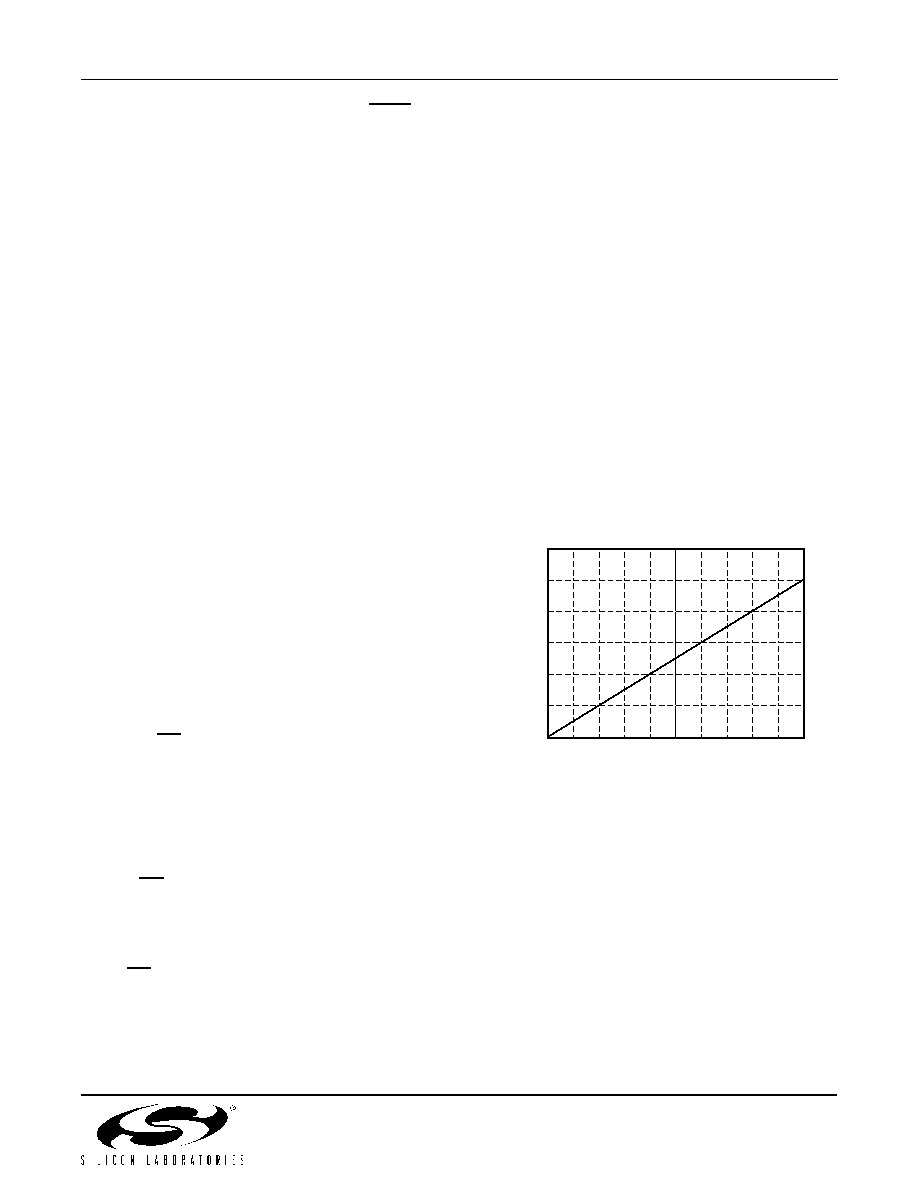
5.11. DC Termination
The DAA has programmable settings for dc impedance,
minimum operational loop current, and TIP/RING
voltage. The dc impedance of the DAA is normally
represented with a 50
slope as shown in Figure 20,
but can be changed to an 800
slope by setting the
DCR bit. This higher dc termination presents a higher
resistance to the line as loop current increases.
.
Figure 20. FCC Mode I/V Characteristics,
DCV[1:0] = 11, MINI[1:0] = 00, ILIM = 0
For applications that require current limiting per the
TBR21 standard, the ILIM bit can be set to select this
mode. In the current limiting mode, the dc I/V curve is
changed to a 2000
slope above 40 mA, as shown in
Figure 21. The DAA operates with a 50 V, 230
feed,
which is the maximum line feed specified in the TBR21
standard.
12
11
10
9
8
7
6
.01 .02 .03 .04 .05 .06 .07 .08 .09 .1 .11
Loop Current (A)
FCC DCT Mode
Voltage
Ac
ro
ss
DAA
(
V
)
相关PDF资料 |
PDF描述 |
|---|---|
| VE-2N3-IX-F4 | CONVERTER MOD DC/DC 24V 75W |
| VE-2N3-IX-F3 | CONVERTER MOD DC/DC 24V 75W |
| DS2251T-64-16# | IC MCU 64KB 16MHZ 72-SIMM |
| AD5700BCPZ-RL7 | IC HART MODEM LP 24LFCSP |
| DS2251T-64-16 | IC MICROCNTRLR 64K 16MHZ 72-SIMM |
相关代理商/技术参数 |
参数描述 |
|---|---|
| Si3018-F-FT | 功能描述:电信线路管理 IC Si3050 Global Voice DAA Line-Side RoHS:否 制造商:STMicroelectronics 产品:PHY 接口类型:UART 电源电压-最大:18 V 电源电压-最小:8 V 电源电流:30 mA 最大工作温度:+ 85 C 最小工作温度:- 40 C 安装风格:SMD/SMT 封装 / 箱体:VFQFPN-48 封装:Tray |
| SI3018-F-FTR | 制造商:Silicon Laboratories Inc 功能描述:SI3050 GLOBAL VOICE DAA LINE-SIDE - LEAD-FREE - Tape and Reel |
| SI3018-F-GM | 制造商:SILABS 制造商全称:SILABS 功能描述:PROGRAMMABLE VOICE DAA SOLUTIONS |
| Si3018-F-GS | 功能描述:电信线路管理 IC Si2415 ISOmodem Line-Side RoHS:否 制造商:STMicroelectronics 产品:PHY 接口类型:UART 电源电压-最大:18 V 电源电压-最小:8 V 电源电流:30 mA 最大工作温度:+ 85 C 最小工作温度:- 40 C 安装风格:SMD/SMT 封装 / 箱体:VFQFPN-48 封装:Tray |
| SI3018-F-GSR | 功能描述:电信线路管理 IC Si2415 ISOmodem Line-Side RoHS:否 制造商:STMicroelectronics 产品:PHY 接口类型:UART 电源电压-最大:18 V 电源电压-最小:8 V 电源电流:30 mA 最大工作温度:+ 85 C 最小工作温度:- 40 C 安装风格:SMD/SMT 封装 / 箱体:VFQFPN-48 封装:Tray |
发布紧急采购,3分钟左右您将得到回复。