- 您现在的位置:买卖IC网 > PDF目录16210 > SI3050PPT2-EVB (Silicon Laboratories Inc)BOARD EVAL FOR DAA SI3050/SI3008 PDF资料下载
参数资料
| 型号: | SI3050PPT2-EVB |
| 厂商: | Silicon Laboratories Inc |
| 文件页数: | 3/16页 |
| 文件大小: | 0K |
| 描述: | BOARD EVAL FOR DAA SI3050/SI3008 |
| 标准包装: | 1 |
| 主要目的: | 电信,数据采集装置(DAA) |
| 已用 IC / 零件: | Si3050 |
| 已供物品: | 板,CD |
�� �
�
�Si3050-EVB�
�2.� Configuring� the� Si-LINK�
�The� Si-LINK� motherboard� is� used� to� interface� the�
�Si3050� to� a� PC� or� other� audio� system� for� easy�
�evaluation.� It� uses� an� FPGA� to� translate� the� parallel� port�
�interface� to� either� SPI/PCM,� SPI-only,� or� GCI� to�
�communicate� with� the� Si3050.�
�When� in� SPI/PCM� mode,� the� PCM� audio� data� and� SPI�
�control� data� are� communicated� from� the� controlling� PC�
�using� the� aforementioned� software.� This� mode� allows�
�the� user� to� evaluate� the� DAA� without� any� lab� equipment�
�other� than� a� PC.�
�By� selecting� SPI-only� operation,� the� PC� is� still� used� to�
�control� the� DAA� through� the� SPI� bus,� but� the� PCM�
�By� changing� the� jumper� configuration� prior� to� powering�
�the� board,� the� mode� of� the� board� can� be� set� according�
�to� Tables� 1–3.�
�JP10� is� the� sixth� jumper� on� the� Si-LINK� motherboard.�
�Moving� this� jumper� to� the� INT� position� routes� pin� 9� of�
�the� Si3050� to� the� Si-LINK� motherboard.� When� the�
�jumper� is� in� the� AOUT� position,� this� signal� is� routed� to�
�the� optional� call� progress� speaker� system,� which� is� not�
�populated� by� default� on� the� evaluation� platform.� Refer� to�
�the� AOUT� PWM� circuit� in� the� Si3050� data� sheet� for�
�values� used� to� populate� this� circuit.�
�Table� 1.� PCM� or� GCI� Highway� Mode� Selection�
�audio� data� is� routed� from� an� external� source.� This�
�external� source� may� be� an� Audio� Precision� system�
�using� the� P1� and� P2� headers� or� a� PCM� highway� using�
�the� BNC� connectors,� J5–J8� (not� populated).�
�To� evaluate� the� Si3050’s� operation� with� the� GCI�
�interface,� the� PC� may� be� used� to� send� the� audio� data�
�and� control.� The� FPGA� performs� the� necessary�
�SCLK�
�1�
�0�
�0�
�SDI�
�X�
�0�
�1�
�Mode� Selected�
�PCM� Mode�
�GCI� Mode,�
�B2� Channel� used�
�GCI� Mode,�
�B1� Channel� used�
�translation� to� communicate� to� the� Si3050� in� this� mode.�
�The� fourth� mode� of� operation� is� the� pass-thru� mode.� In�
�this� mode,� the� FPGA� is� only� used� to� route� the� GCI� bus�
�to� the� Audio� Precision� or� BNC� headers� on� the� Si-LINK�
�board.� In� this� mode,� a� PC� is� not� required� to� control� the�
�evaluation� platform.�
�Note:� Values� shown� are� the� states� of� the� pins� at� the�
�rising� edge� of� RESET.�
�Table� 2.� Pin� Functionality� in� PCM� or� GCI�
�Highway� Mode�
�Pin� Name�
�PCM� Mode�
�GCI� Mode�
�Mode�
�SPI/PCM�
�SPI-Only�
�GCI�
�JP3� (Source)�
�0�
�1�
�0�
�JP4� (Format)�
�0�
�0�
�1�
�SDI_THRU� SPI� Data� Through-�
�put� pin� for� Daisy�
�Chaining� Operation�
�(Connects� to� the� SDI�
�pin� of� the� subse-�
�quent� device� in� the�
�daisy� chain)�
�Sub-frame�
�Selector,� bit� 2�
�Pass-Thru�
�1�
�1�
�SCLK�
�SPI� Clock� Input�
�PCM/GCI� Mode�
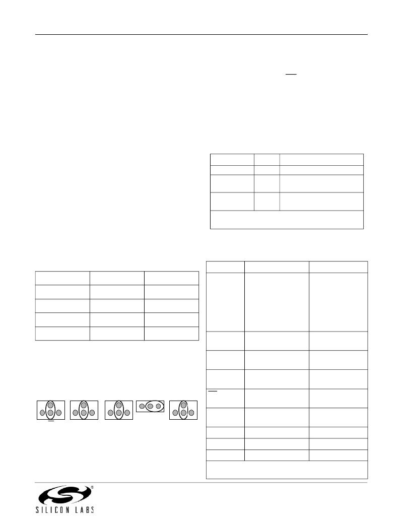
�3.� Configuring� the� Si3050DC-EVB�
�The� Si3050DC-EVB� has� six� jumpers.� The� first� five�
�control� the� boot-strap� options� for� configuring� the�
�Si3050.� The� default� state� is� set� to� allow� the� Si3050� to� be�
��SDI�
�SDO�
�Selector�
�SPI� Serial� Data� Input� B1/B2� Channel�
�Selector�
�SPI� Serial� Data� Out-� Sub-frame�
�put� Selector,� bit� 1�
�CS�
�SPI� Chip� Select�
�Sub-frame�
�Selector,� bit� 0�
�0� SDI_THRU� 1�
�FSYNC�
�PCM� Frame� Sync�
�GCI� Frame� Sync�
�0�
�CS�
�1�
�0� SCLK� 1�
�0� SDO� 1�
�0�
�SDI�
�1�
�Input�
�Input�
�Figure� 1.� SPI� Control� Mode� Default� State�
�PCLK�
�DTX�
�DRX�
�PCM� Input� Clock�
�PCM� Data� Transmit�
�PCM� Data� Receive�
�GCI� Input� Clock�
�GCI� Data� Transmit�
�GCI� Data� Receive�
�Note:� This� table� denotes� pin� functionality� after� the� rising�
�edge� of� RESET� and� mode� selection.�
�Rev.� 1.1�
�3�
�相关PDF资料 |
PDF描述 |
|---|---|
| CW252016-47NG | INDUCTOR 47NH 1008 SMD |
| SI3056DC-EVB | DAUGHTERCARD DAA SI3056/SI3018 |
| GBM31DCCI | CONN EDGECARD 62POS R/A .156 SLD |
| CW252016-39NG | INDUCTOR 39NH 1008 SMD |
| CW252016-33NG | INDUCTOR 33NH 1008 SMD |
相关代理商/技术参数 |
参数描述 |
|---|---|
| Si3050PPT-EVB | 功能描述:界面开发工具 Voice DAA Parallel Port Eval Board RoHS:否 制造商:Bourns 产品:Evaluation Boards 类型:RS-485 工具用于评估:ADM3485E 接口类型:RS-485 工作电源电压:3.3 V |
| SI-3050R | 制造商:SANKEN 制造商全称:Sanken electric 功能描述:5-Terminal, Multi-Function, Full-Mold, Low Dropout Voltage Dropper Type with Reset Function |
| SI-3051N | 制造商:ALLEGRO 制造商全称:Allegro MicroSystems 功能描述:LOW-VOLTAGE, HIGH-CURRENT 1.8 V LINEAR REGULATOR |
| SI-3052 | 制造商:SANKEN 制造商全称:Sanken electric 功能描述:3-Terminal, Low Dropout Voltage Dropper Type |
| SI-3052N | 制造商:SANKEN 制造商全称:Sanken electric 功能描述:3-Terminal, Full-Mold, Low Dropout Voltage Dropper Type |
发布紧急采购,3分钟左右您将得到回复。