- 您现在的位置:买卖IC网 > PDF目录20644 > SI786CRG-T1-E3 (Vishay Siliconix)IC REG QD BUCK/LINEAR 28SSOP PDF资料下载
参数资料
| 型号: | SI786CRG-T1-E3 |
| 厂商: | Vishay Siliconix |
| 文件页数: | 13/16页 |
| 文件大小: | 236K |
| 描述: | IC REG QD BUCK/LINEAR 28SSOP |
| 标准包装: | 1,800 |
| 拓扑: | 降压(降压)(2),线性(LDO)(2) |
| 功能: | 任何功能 |
| 输出数: | 4 |
| 频率 - 开关: | 300kHz,200kHz |
| 电压/电流 - 输出 1: | 控制器 |
| 电压/电流 - 输出 2: | 控制器 |
| 电压/电流 - 输出 3: | 5V,5mA |
| 带 LED 驱动器: | 无 |
| 带监控器: | 无 |
| 带序列发生器: | 无 |
| 电源电压: | 5.5 V ~ 30 V |
| 工作温度: | 0°C ~ 70°C |
| 安装类型: | 表面贴装 |
| 封装/外壳: | 28-SSOP(0.209",5.30mm 宽) |
| 供应商设备封装: | 28-SSOP |
| 包装: | 带卷 (TR) |
Document Number: 70189
S-40807-Rev. J, 26-Apr-04
www.vishay.com
13
Vishay Siliconix
Si786
Product is End of Life 3/2014
Oscillator and SYNC
There are two ways to set the Si786 oscillator frequency: by
using an external SYNC signal, or using the internal oscilla-
tor. The SYNC pin can be driven with an external CMOS
level signal with frequency from 240 kHz and 350 kHz to syn-
chronize to the internal oscillator. Tying SYNC to either V
L
or
GND sets the frequency to 200 kHz and to REF sets the fre-
quency to 300 kHz.
Operation at 300 kHz is typically used to minimize output
passive component sizes. Slower switching speeds of
200kHz may be needed for lower input voltages.
Internal V
L
and REF
A 5 V linear regulator supplies power to the internal logic cir-
cuitry. The regulator is available for external use from pin V
L
,
able to source 5 mA. A 10 礔 capacitor should be connected
between V
L
and GND. To increase efficiency, when the 5 V
switching supply has voltage greater than 4.5 V, V
L
is inter-
nally switched over to the output of the 5 V switching supply
and the linear regulator is turned off.
The 5 V linear regulator provides power to the internal 3.3 V
bandgap reference (REF). The 3.3 V reference can supply
5mA to an external load, connected to pin REF. Between
REF and GND connect a capacitor, 0.22 礔 plus 1 礔 per mA
of load current. The switching outputs will vary with the refer-
ence; therefore, placing a load on the REF pin will cause the
main outputs to decrease slightly, within the specified regu-
lation tolerance.
V
L
and REF supplies stay on as long as V+ is greater than
4.5 V, even if the switching supplies are not enabled. This
feature is necessary when using the micropower regulators
to keep memory alive during shutdown.
Both linear regulators can be connected to their respective
switching supply outputs. For example, REF would be tied to
the output of the 3.3 V and V
L
to 5 V. This will keep the main
supplies up in standby mode, provided that each load current
in shutdown is not larger than 5 mA.
Fault Protection
The 3.3 V and 5 V switching controllers as well as the com-
parators are shut down when one of the linear regulators
drops below 85 % of its nominal value; that is, shut down will
occur when V
L
< 4.0 V or REF < 2.8 V.
DESIGN CONSIDERATIONS
Inductor Design
Three specifications are required for inductor design: induc-
tance (L), peak inductor current (I
LPEAK
), and coil resistance
(R
L
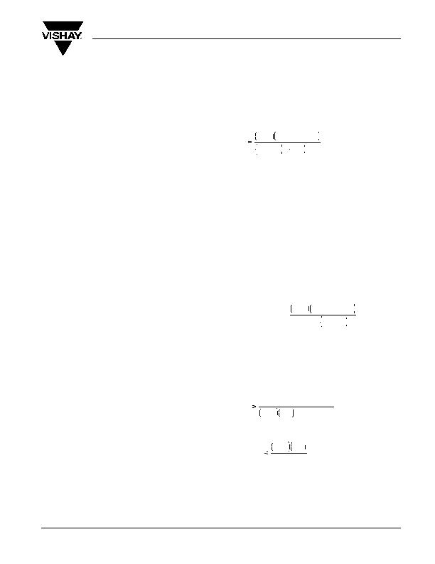
). The equation for computing inductance is:
Where: V
OUT
= Output voltage (3.3 V or 5 V);
V
IN(MAX)
= Maximum input voltage (V);
f = Switching frequency, normally 300 kHz;
I
OUT
= Maximum dc load current (A);
LIR = Ratio of inductor peak-to-peak ac current to
average dc load current, typically 0.3.
When LIR is higher, smaller inductance values are accept-
able, at the expense of increased ripple and higher losses.
The peak inductor current (I
LPEAK
) is equal to the steady-
state load current (I
OUT
) plus one half of the peak-to-peak ac
current (I
LPP
). Typically, a designer will select the ac inductor
current to be 30 % of the steady-state current, which gives
I
LPEAK
equal to 1.15 times I
OUT
.
The equation for computing peak inductor current is:
Output Capacitors
The output capacitors determine loop stability and ripple volt-
age at the output. In order to maintain stability, minimum
capacitance and maximum ESR requirements must be met
according to the following equations:
and,
Where: C
F
= Output filter capacitance (F)
V
REF
= Reference voltage, 3.3 V;
V
OUT
= Output voltage, 3.3 V or 5 V;
R
CS
= Sense resistor (?;
GBWP = Gain-bandwidth product, 60 kHz;
ESR
CF
= Output filter capacitor ESR (?.
V
OUT
V
IN(MAX)
- V
OUT
V
INMAX
(
f
)
I
T
(
LIR
)
I
LPEAK
I
OUT
V
OUT
V
IN(MAX)
- V
OUT
(2)(f)(L)
V
IN(MAX)
+
F
V
REF
V
T
R
(2)(?(GBWP)
SR
CF
V
OUT
R
CS
V
REF
相关PDF资料 |
PDF描述 |
|---|---|
| FEP16GTD | DIODE FAST 400V 8A DBLR TO220AB |
| NMN0.88BK50 | NYLON MULTI 7/8" BLACK 50' |
| AMM24DRKI-S13 | CONN EDGECARD 48POS .156 EXTEND |
| SI786CG-T1-E3 | IC REG QD BUCK/LINEAR 28SSOP |
| VI-J5F-CX-F1 | CONVERTER MOD DC/DC 72V 75W |
相关代理商/技术参数 |
参数描述 |
|---|---|
| SI786CSG | 功能描述:DC/DC 开关控制器 3.6V Power Sup Cont RoHS:否 制造商:Texas Instruments 输入电压:6 V to 100 V 开关频率: 输出电压:1.215 V to 80 V 输出电流:3.5 A 输出端数量:1 最大工作温度:+ 125 C 安装风格: 封装 / 箱体:CPAK |
| SI786CSG-E3 | 功能描述:开关变换器、稳压器与控制器 Dual 3.6V Step-Down RoHS:否 制造商:Texas Instruments 输出电压:1.2 V to 10 V 输出电流:300 mA 输出功率: 输入电压:3 V to 17 V 开关频率:1 MHz 工作温度范围: 安装风格:SMD/SMT 封装 / 箱体:WSON-8 封装:Reel |
| SI786CSG-T1 | 功能描述:开关变换器、稳压器与控制器 Dual 3.6V Step-Down RoHS:否 制造商:Texas Instruments 输出电压:1.2 V to 10 V 输出电流:300 mA 输出功率: 输入电压:3 V to 17 V 开关频率:1 MHz 工作温度范围: 安装风格:SMD/SMT 封装 / 箱体:WSON-8 封装:Reel |
| SI786CSG-T1-E3 | 功能描述:开关变换器、稳压器与控制器 Dual 3.6V Step-Down RoHS:否 制造商:Texas Instruments 输出电压:1.2 V to 10 V 输出电流:300 mA 输出功率: 输入电压:3 V to 17 V 开关频率:1 MHz 工作温度范围: 安装风格:SMD/SMT 封装 / 箱体:WSON-8 封装:Reel |
| SI786DB | 功能描述:电源管理IC开发工具 SI786 Demo Board RoHS:否 制造商:Maxim Integrated 产品:Evaluation Kits 类型:Battery Management 工具用于评估:MAX17710GB 输入电压: 输出电压:1.8 V |
发布紧急采购,3分钟左右您将得到回复。