- 您现在的位置:买卖IC网 > PDF目录66246 > SML1209-0ER-TR (LEDTRONICS INC) T-3/4 SINGLE COLOR LED, SUPER RED, 1.8 mm PDF资料下载
参数资料
| 型号: | SML1209-0ER-TR |
| 厂商: | LEDTRONICS INC |
| 元件分类: | LED |
| 英文描述: | T-3/4 SINGLE COLOR LED, SUPER RED, 1.8 mm |
| 文件页数: | 7/9页 |
| 文件大小: | 1786K |
| 代理商: | SML1209-0ER-TR |
Part No.
Page
7 of 9
SML1209-0ER-TR
23105 Kashiwa Court, Torrance, CA 90505
Phone: (800) 579-4875 or (310) 534-1505 Fax: (310) 534-1424
E-mail: webmaster@ledtronics.com
Website: http://www.ledtronics.com
DSTR0210
DWG NO.
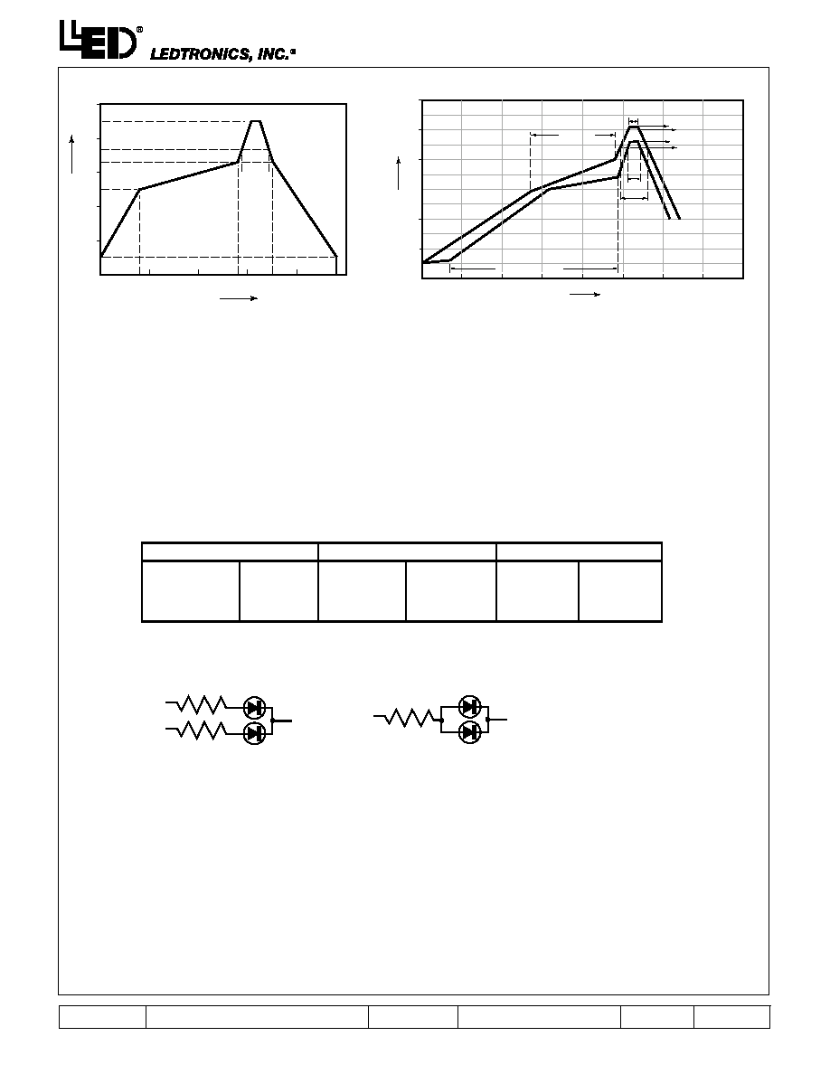
Reflow Profile Temp/Time
140
sec
125°C
165°C
183°C
225°C
162
sec
40
sec
ABOVE
183°C
90sec
max
25°C
150
Time
200
250
(sec)
50
Z1
R1
R2
R3
R4
R5
Z2
Z3
Z4
50
100
150
Temperature
200
250
(°C)
0
100
0
4. Soldering
Recommended soldering conditions:
(A) Recommended circuit.
(B) The brightness of each LED might appear different due to the differences in the I-V characteristics
of those LEDs.
6. ESD (Electrostatic Discharge)
Static Electricity or power surge will damage the LED.
Suggestions to prevent ESD damage:
Use of a conductive wrist band or anti-electrostatic glove when handling these LEDs.
All devices, equipment, and machinery must be properly grounded.
Work tables, storage racks, etc. should be properly grounded.
Use ion blower to neutralize the static charge which might have built up on surface of the LED’s
plastic lens as a result of friction between LEDs during storage and handling.
LED
300°C Max.
3 sec. Max.
(one time only)
Temperature
Soldering time
100°C Max.
60 sec. Max.
260°C Max.
10 sec. Max.
Pre-heat
Pre-heat time
Solder wave
Soldering time
120~150°C
120 sec. Max.
240°C Max.
10 sec. Max.
Pre-heat
Pre-heat time
Peak temperature
Soldering time
Reflow soldering
Wave Soldering
Soldering Iron
Circuit model A
Circuit model B
ESD-damaged LEDs will exhibit abnormal characteristics such as high reverse leakage current, low forward
voltage, or “no lightup” at low currents.
To verify for ESD damage, check for “lightup” and Vf of the suspect LEDs at low currents.
The Vf of “good” LEDs should be >2.0V@0.1mA for InGaN products and >1.4V@0.1mA for AlInGaP products.
Recommended P rofile Between Assemble And Heat-Resistance Line
(2) Suggestion IR Reflow Profile For Pb Free Process
The Profile is available that must use SnAg(x=3.3~3.8) Cu(y=0.2~0.7) solder paste
Pre-Heat
140°C~200°C
60~120 sec.
160°C More than 60 sec.
More than
200°C
10~40 sec.
150
Time
200
250
300
400
(sec)
350
50
100
150
Temperature
200
250
300
(°C)
0
100
0
Peak Temp. 255°C
250°C
Peak Temp. 230°C
220°C
255°C
10 s max.
1. Application
The LEDs described here are intended to be used for ordinary electronic equipment (such as office equipment, communication
equipment and household applications).Consult LEDtronics in advance for information on applications in which exceptional
reliability is required, particularly when the failure or malfunction of the LEDs may directly jeopardize life or health (such as in
aviation, transportation, traffic control equipment, medical dical and life support systems and safety devices).
2. Storage
The storage ambient for the LEDs should not exceed 30°C temperature or 70% relative humidity. It is recommended that LEDs
out of their original packaging are IR-reflowed within one week. For extended storage out of their original packaging, it is recom-
mended that the LEDs be stored in a sealed container with appropriate desiccant, or in a desiccators with nitrogen ambient. LEDs
stored out of their original packaging for more than a week should be baked at about 60° C for at least 24 hours before solder
assembly.
3. Cleaning Use alcohol-based cleaning solvents such as isopropyl alcohol to clean the LED if necessary.
5. Drive Method
An LED is a current-operated device. In order to ensure intensity uniformity on multiple LEDs connected in parallel in an
application, it is recommended that a current limiting resistor be incorporated in the drive circuit, in series with each LED as
shown in Circuit A below.
相关PDF资料 |
PDF描述 |
|---|---|
| SML1209-0PY-TR | T-3/4 SINGLE COLOR LED, SUPER YELLOW, 1.8 mm |
| SML1209-0UG-TR | T-3/4 SINGLE COLOR LED, SUPER LUMINOSITY GREEN, 1.8 mm |
| SML1209M-0PY-TR | SINGLE COLOR LED |
| SML12G1KH-TR | DUAL COLOR LED, YELLOW/GREEN, 2.7 mm |
| SML12G4C | SINGLE COLOR LED, ULTRA GREEN, 2.4 mm |
相关代理商/技术参数 |
参数描述 |
|---|---|
| SML120B10 | 制造商:SEME-LAB 制造商全称:Seme LAB 功能描述:N-CHANNEL ENHANCEMENT MODE HIGH VOLTAGE POWER MOSFETS |
| SML120J15 | 制造商:SEME-LAB 制造商全称:Seme LAB 功能描述:N-CHANNEL ENHANCEMENT MODE HIGH VOLTAGE POWER MOSFETS |
| SML120J25 | 制造商:SEME-LAB 制造商全称:Seme LAB 功能描述:N-CHANNEL ENHANCEMENT MODE HIGH VOLTAGE POWER MOSFETS |
| SML120L16 | 制造商:SEME-LAB 制造商全称:Seme LAB 功能描述:N-CHANNEL ENHANCEMENT MODE HIGH VOLTAGE POWER MOSFETS |
| SML1216C | 制造商:SANKEN 制造商全称:Sanken electric 功能描述:5phi Round Standard Bicolor LED |
发布紧急采购,3分钟左右您将得到回复。