- 您现在的位置:买卖IC网 > PDF目录54481 > SMP1307-005 SILICON, PIN DIODE PDF资料下载
参数资料
| 型号: | SMP1307-005 |
| 元件分类: | PIN二极管 |
| 英文描述: | SILICON, PIN DIODE |
| 文件页数: | 1/4页 |
| 文件大小: | 498K |
| 代理商: | SMP1307-005 |
Alpha Industries, Inc. [781] 935-5150
Fax [617] 824-4579 Email sales@alphaind.com www.alphaind.com
1
Specifications subject to change without notice. 1/01A
Very Low Distortion Attenuator
Plastic Packaged PIN Diodes
Features
s Low Distortion Design
s Frequency Range from HF to > 2 GHz
s Designed for CATV AGC Applications
s Designed for High Volume Wireless
Applications
Description
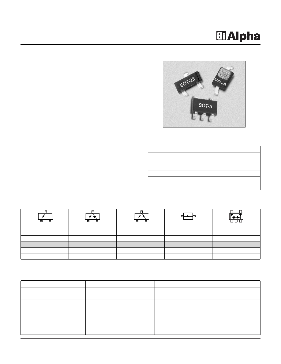
The SMP1307 series of plastic packaged, surface
mountable, low capacitance (0.3 pF) silicon PIN diodes
are designed for use in attenuator applications from 5 MHz
to beyond 2 GHz. The thick 175
m I region of these PIN
diodes makes them very attractive for use in very low
distortion PI and TEE attenuators commonly used in TV
distribution applications. The 1.5
S typical carrier
lifetime of these diodes results in resistance of 100
maximum at 1 mA and 10
maximum at 10 mA. Available
in a selection of plastic packages, as a single diode in the
small footprint SOD-323, and in a variety of configurations
in the SOT-23. Also available in a SOT-5 (SMP1307-027)
package as a four diode array designed for insertion in the
commonly used 4 diode PI attenuator circuit.
SMP1307 Series
Characteristic
Value
Reverse Voltage (VR)
200 V
Power Dissipation @ 25°C Lead
250 mW
Temperature (PD)
Storage Temperature (TST)
-65°C to +150°C
Operating Temperature (TOP)
-65°C to +150°C
ESD Human Body Model
Class 1C
Absolute Maximum Ratings
Single
Common
Series Pair
Single
PI
Cathode
Marking: PJ1
Marking: PJ3
Marking: PJ2
Marking: PJM
SOT-23
SOD-323
SOT-5
o
SMP1307-001
o
SMP1307-004
o
SMP1307-005
o
SMP1307-011
o
SMP1307-027
LS = 1.5 nH
o Available through distribution.
Parameter
Condition
Typ.
Max.
Unit
Reverse Current (IR)VR = 200 V
10
A
Capacitance (CT)
F = 1 MHz, V = 30 V
0.30
pF
Resistance (RS)
F = 100 MHz, I = 1 mA
75
100
Resistance (RS)
F = 100 MHz, I = 10 mA
15
Resistance (RS)
F = 100 MHz, I = 100 mA
3.0
Forward Voltage (VF)
IF = 10 mA
0.85
V
Carrier Lifetime (TI)
IF = 10 mA
1.5
S
I Region Width
175
m
Electrical Specifications at 25°C
相关PDF资料 |
PDF描述 |
|---|---|
| SMP1307-004 | SILICON, PIN DIODE |
| SMP1322-007 | SILICON, PIN DIODE |
| SMP1322-079 | SILICON, PIN DIODE |
| SMP1324-087LF | SILICON, PIN DIODE |
| SMP1330-005 | 20 V, SILICON, PIN DIODE |
相关代理商/技术参数 |
参数描述 |
|---|---|
| SMP1307-005LF | 功能描述:PIN 二极管 Ls-1.5nH SOT-23 Series Pair RoHS:否 制造商:Skyworks Solutions, Inc. 配置: 反向电压:200 V 正向连续电流: 频率范围:10 MHz to 6 GHz 端接类型:SMD/SMT 封装 / 箱体:QFN-3 封装:Reel |
| SMP1307-005LF-B | 制造商:Skyworks Solutions Inc 功能描述:RF PIN DIODE |
| SMP1307-006LF | 功能描述:PIN 二极管 Ls-1.5nH SOT-23 Reverse Series Pair RoHS:否 制造商:Skyworks Solutions, Inc. 配置: 反向电压:200 V 正向连续电流: 频率范围:10 MHz to 6 GHz 端接类型:SMD/SMT 封装 / 箱体:QFN-3 封装:Reel |
| SMP1307-006LF-B | 制造商:Skyworks Solutions Inc 功能描述:RF PIN DIODE |
| SMP1307-011 | 制造商:SKYWORKS 制造商全称:SKYWORKS 功能描述:Very Low Distortion Attenuator Plastic Packaged PIN Diodes |
发布紧急采购,3分钟左右您将得到回复。