- 您现在的位置:买卖IC网 > PDF目录384927 > SMS48GR07 (Summit Microelectronics, Inc.) Quad Programmable Precision Supervisory Controller With Independent Resets PDF资料下载
参数资料
| 型号: | SMS48GR07 |
| 厂商: | Summit Microelectronics, Inc. |
| 英文描述: | Quad Programmable Precision Supervisory Controller With Independent Resets |
| 中文描述: | 四可编程精密监控控制器,独立重置 |
| 文件页数: | 12/16页 |
| 文件大小: | 848K |
| 代理商: | SMS48GR07 |
12
SMS48
2088 1.1 04/10/05
SUMMIT MICROELECTRONICS, Inc.
Preliminary Information
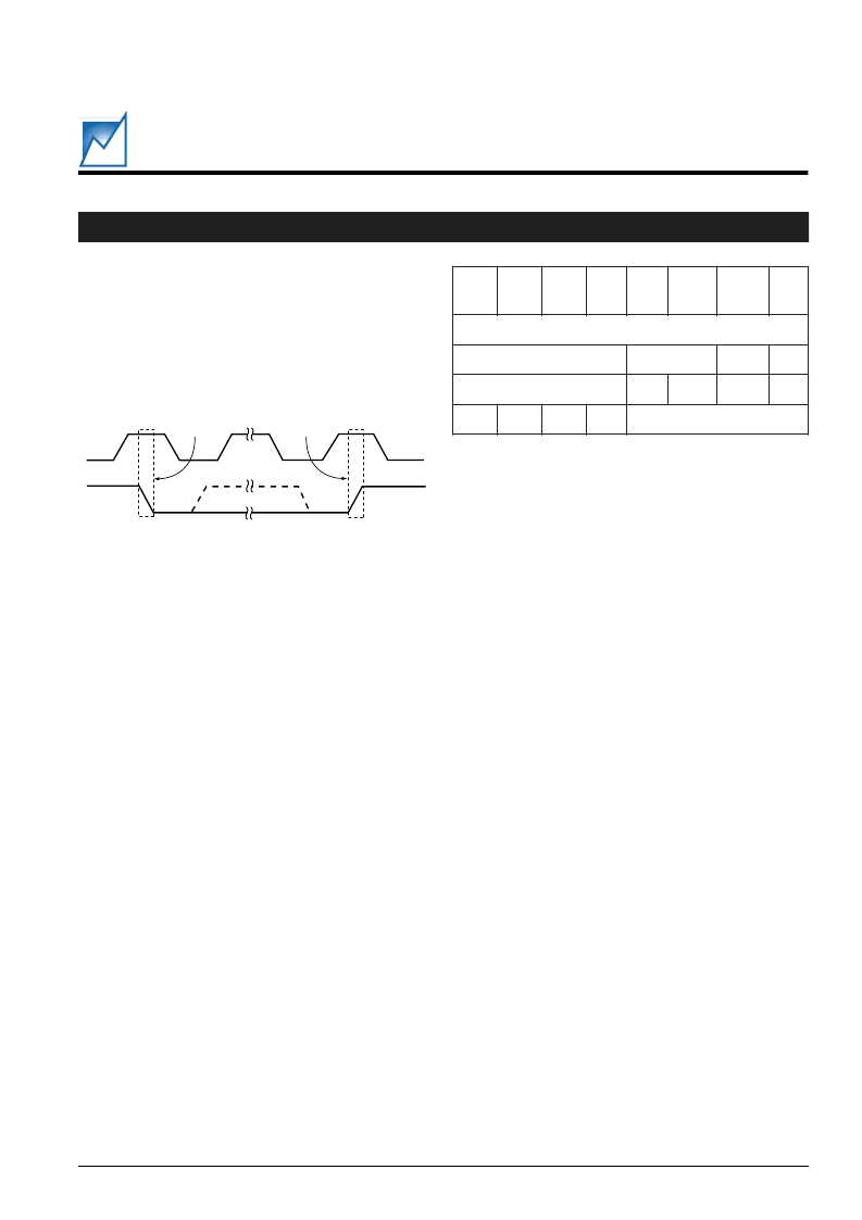
Figure 8 - START and STOP Conditions
Table 9. Slave Addresses
START and STOP Conditions
When both the data and clock lines are high the bus is said
to be not busy. A high-to-low transition on the data line,
while the clock is high, is defined as the Start condition.
A low-to-high transition on the data line, while the clock
is high, is defined as the Stop condition. See Figure 8.
Acknowledge (ACK)
Acknowledge is a software convention used to indicate
successful data transfers. The transmitting device,
either the Master or the Slave, will release the bus after
transmitting eight bits. During the ninth clock cycle the
receiver will pull the SDA line low to Acknowledge that it
received the eight bits of data. The Master will leave the
SDA line high (NACK) when it terminates a read function.
The SMS48 will respond with an Acknowledge after recog-
nition of a Start condition and its slave address byte. If both
the device and a write operation are selected the SMS48
will respond with an Acknowledge after the receipt of each
subsequent 8-Bit word. In the READ mode the SMS48
transmits eight bits of data, then releases the SDA line, and
monitors the line for an Acknowledge signal. If an Acknowl-
edge is detected and no Stop condition is generated by the
Master, the SMS48 will continue to transmit data. If a
NACK is detected the SMS48 will terminate further data
transmissions and await a Stop condition before returning
to the standby power mode.
Device Addressing
Following a Start condition the Master must output the
address of the Slave it is accessing. The most significant
four bits of the Slave address are the device type
identifier/address. For the SMS48 the default is 1001
BIN
.
The next two bits are the Bus Address. The next bit (the
7th) is the MSB of the configuration address.
Read/Write Bit
The last bit of the data stream defines the operation to be
performed. When set to 1 a Read operation is selected;
when set to 0 a Write operation is selected.
WRITE OPERATIONS
The SMS48 uses byte Write operations. A byte Write
operation writes a single byte during the nonvolatile write
period (t
WR
).
Byte Write
After the Slave address is sent (to identify the Slave device
and select either a Read or Write operation), a second byte
is transmitted which contains the low order 8 bit address
of any one of the 256 words in the array. Upon receipt of
the word address the SMS48 responds with an Acknowl-
edge. After receiving the next byte of data it again
responds with an Acknowledge. The Master then termi-
nates the transfer by generating a Stop condition, at which
time the SMS48 begins the internal Write cycle. While the
internal Write cycle is in progress the SMS48 inputs are
disabled and the device will not respond to any requests
from the Master.
Acknowledge Polling
When the SMS48 is performing an internal Write operation
it will ignore any new Start conditions. Since the device will
only return an acknowledge after it accepts the Start the
part can be continuously queried until an acknowledge is
issued, indicating that the internal Write cycle is complete.
See the flow chart for the proper sequence of operations for
polling.
SCL
SDA In
START
Condition
STOP
Condition
7
D
B
S
M
6
D
5
D
4
D
3
D
2
D
1
D
0
B
D
S
L
s
s
s
e
d
A
e
p
y
e
c
e
D
s
u
B
B
S
M
W
/
8
4
S
M
S
x
x
x
x
1
0
0
1
r
e
R
n
o
g
o
C
I
2
C INTERFACE (CONTINUED)
相关PDF资料 |
PDF描述 |
|---|---|
| SMS64 | Six-Channel Supply Monitor and Sequencing Controller |
| SMS64FR00 | Six-Channel Supply Monitor and Sequencing Controller |
| SMS64FR01 | Six-Channel Supply Monitor and Sequencing Controller |
| SMS64FR02 | Six-Channel Supply Monitor and Sequencing Controller |
| SMS64FR03 | Six-Channel Supply Monitor and Sequencing Controller |
相关代理商/技术参数 |
参数描述 |
|---|---|
| SMS49N1C3E | 制造商:MONITOR_PROD 功能描述: |
| SMS4CSB1 | 功能描述:集管和线壳 Protection Shroud 4P Pnl Mnt Pin Recpt RoHS:否 产品种类:1.0MM Rectangular Connectors 产品类型:Headers - Pin Strip 系列:DF50 触点类型:Pin (Male) 节距:1 mm 位置/触点数量:16 排数:1 安装风格:SMD/SMT 安装角:Right 端接类型:Solder 外壳材料:Liquid Crystal Polymer (LCP) 触点材料:Brass 触点电镀:Gold 制造商:Hirose Connector |
| SMS4GE3 | 功能描述:集管和线壳 4P QIKMATE SOCKET STRT PC BOARDMOUNT RoHS:否 产品种类:1.0MM Rectangular Connectors 产品类型:Headers - Pin Strip 系列:DF50 触点类型:Pin (Male) 节距:1 mm 位置/触点数量:16 排数:1 安装风格:SMD/SMT 安装角:Right 端接类型:Solder 外壳材料:Liquid Crystal Polymer (LCP) 触点材料:Brass 触点电镀:Gold 制造商:Hirose Connector |
| SMS4GE3D70 | 制造商:未知厂家 制造商全称:未知厂家 功能描述:Trim Trio Interconnection System |
| SMS4GE3J | 功能描述:集管和线壳 4P Socket Straight Boardmount RoHS:否 产品种类:1.0MM Rectangular Connectors 产品类型:Headers - Pin Strip 系列:DF50 触点类型:Pin (Male) 节距:1 mm 位置/触点数量:16 排数:1 安装风格:SMD/SMT 安装角:Right 端接类型:Solder 外壳材料:Liquid Crystal Polymer (LCP) 触点材料:Brass 触点电镀:Gold 制造商:Hirose Connector |
发布紧急采购,3分钟左右您将得到回复。