- 您现在的位置:买卖IC网 > PDF目录384927 > SMS64FR07 (Summit Microelectronics, Inc.) Six-Channel Supply Monitor and Sequencing Controller PDF资料下载
参数资料
| 型号: | SMS64FR07 |
| 厂商: | Summit Microelectronics, Inc. |
| 英文描述: | Six-Channel Supply Monitor and Sequencing Controller |
| 中文描述: | 6通道电源监视器和排序控制器 |
| 文件页数: | 7/24页 |
| 文件大小: | 647K |
| 代理商: | SMS64FR07 |
SMS64
Preliminary
Summit Microelectronics, Inc
2060 2.22 10/09/03
7
ABSOLUTE MAXIMUM RATINGS
Temperature Under Bias ...................... -55
°
C to 125
°
C
Storage Temperature............................ -65
°
C to 150
°
C
Terminal Voltage with Respect to GND:
VCC
A
, VCC
B
, VCC
C
, VCC
D
, VCC
E
, VCC
F
..-0.3V to 6.0V
VM
A
, VM
B
, VM
C
, VM
D
, VM
E
, VM
F
...............-0.3V to 6.0V
PUP
A
, PUP
B
, PUP
C
, PUP
D,
PUP
E
, PUP
F
..............15.5V
All Others......................................................V
CC
+ 0.7V
Output Short Circuit Current...............................100mA
Lead Solder Temperature (10 secs)....................300
°
C
ESD Rating per JEDEC…………………………..2000V
Latch-Up testing per JEDEC……………......+/- 100mA
RECOMMENDED OPERATING CONDITIONS
Temperature Range(Ambient)...……-40
°
C to +85
°
C
Supply Voltage………………….………2.7V to 6.0V
1/
Package Thermal Resistance (
θ
JA)
48 Lead SSOP…………………………………80
o
C/W
Moisture Classification Level 1 (MSL 1) per J-STD- 020
RELIABILITY CHARACTERISTICS
Data Retention…………………………..…..100 Years
Endurance…………………….……….100,000 Cycles
Stresses listed under Absolute Maximum Ratings may cause permanent
damage to the device. These are stress ratings only and functional operation
of the device at these or any other conditions outside those listed in the
operational sections of the specification is not implied. Exposure to any
absolute maximum rating for extended periods may affect device performance
and reliability. Devices are ESD sensitive. Handling precautions are
recommended.
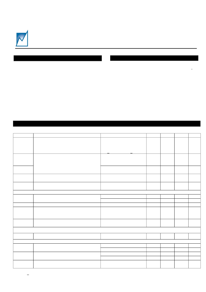
DC OPERATING CHARACTERISTICS
(Over recommended operating conditions, unless otherwise noted. All voltages are relative to GND.)
Symbol
Parameter
Device supply voltage
defined by the highest of
the six VCC inputs. Must
be > 2.7V. – Note 1/
Active Current with PUP
Outputs configured as
high-side drivers enabled
Power Supply Current
Quiescent Current high-
side PUP Outputs disabled
Programmable Threshold (VCC and VM
Inputs)
“naked” mode, V input
disconnected from ground
PUP characteristics when configured as high-side driver
Option 1 (MOSFETs on)
P
VPUP
Programmable PUP Output
Option 2 (MOSFETs on)
V
PUP
OFF
PUP Output
I
PUPSINK
= 2mA
When configured as high-
side driver and with
MOSFET switches on
When Configured as High
Side Driver
PUP characteristics when configured as a logic output
Notes
Min.
Typ.
Max
Unit
VCC
Supply Voltage VCC
A
, VCC
B
, VCC
C,
VCC
D,
VCC
E,
VCC
F
2.7
6.0
V
I
DD
(ON)
2
mA
I
DD
(Off)
1
mA
P
VIT
8-bit resolution 20mV/bit
0.9
6.0
V
V
TH
Fixed threshold Voltage
0.5
V
14.5
10.5
V
V
V
0
0.4
I
PUP
PUP Drive Current
8
μ
A
SR
PUP
PUP Slew Rate
250
V/s
V
OL
Output Low Voltage
I
SINK
= 2mA
0
0.4
V
All other input and output characteristics
Input High Voltage (FS#, PWR_ON/OFF,
MR#)
Input Low Voltage (FS#, PWR_ON/OFF,
MR#)
Open Drain Outputs (RST_A#, RST_B#,
IRQ#, HEALTHY#)
VCC = 2.7V
VCC = 5.0V
VCC = 2.7V
VCC = 5.0V
0.9xVI
0.7xVI
-0.1
-0.1
VI
VI
V
V
V
V
V
IH
0.1xVI
0.3xVI
V
IL
V
OL
I
SINK
= 2mA
0
0.4
V
Notes: 1/ At least one of the VCC inputs needs to be at or above 2.7V for proper device operation.
相关PDF资料 |
PDF描述 |
|---|---|
| SMS64FR08 | Six-Channel Supply Monitor and Sequencing Controller |
| SMS66 | Six-Channel Power Supply Supervisor and Cacsade Sequence Controller |
| SMS66FR0C | Six-Channel Power Supply Supervisor and Cacsade Sequence Controller |
| SMS66FR0D | Six-Channel Power Supply Supervisor and Cacsade Sequence Controller |
| SMS66FR0E | Six-Channel Power Supply Supervisor and Cacsade Sequence Controller |
相关代理商/技术参数 |
参数描述 |
|---|---|
| SMS64FR08 | 制造商:SUMMIT 制造商全称:SUMMIT 功能描述:Six-Channel Supply Monitor and Sequencing Controller |
| SMS66 | 制造商:SUMMIT 制造商全称:SUMMIT 功能描述:Six-Channel Power Supply Supervisor and Cacsade Sequence Controller |
| SMS66FR0C | 制造商:SUMMIT 制造商全称:SUMMIT 功能描述:Six-Channel Power Supply Supervisor and Cacsade Sequence Controller |
| SMS66FR0D | 制造商:SUMMIT 制造商全称:SUMMIT 功能描述:Six-Channel Power Supply Supervisor and Cacsade Sequence Controller |
| SMS66FR0E | 制造商:SUMMIT 制造商全称:SUMMIT 功能描述:Six-Channel Power Supply Supervisor and Cacsade Sequence Controller |
发布紧急采购,3分钟左右您将得到回复。