- 您现在的位置:买卖IC网 > PDF目录98136 > SN54F30J (TEXAS INSTRUMENTS INC) F/FAST SERIES, 8-INPUT NAND GATE, CDIP14 PDF资料下载
参数资料
| 型号: | SN54F30J |
| 厂商: | TEXAS INSTRUMENTS INC |
| 元件分类: | 门电路 |
| 英文描述: | F/FAST SERIES, 8-INPUT NAND GATE, CDIP14 |
| 封装: | 0.300 INCH, CERAMIC, DIP-16 |
| 文件页数: | 8/15页 |
| 文件大小: | 653K |
| 代理商: | SN54F30J |
SN54F30, SN74F30
8-INPUT POSITIVE-NAND GATES
SDFS043A – MARCH 1987 – REVISED OCTOBER 1993
2–2
POST OFFICE BOX 655303
DALLAS, TEXAS 75265
absolute maximum ratings over operating free-air temperature range (unless otherwise noted)
Supply voltage range, VCC
– 0.5 V to 7 V
. . . . . . . . . . . . . . . . . . . . . . . . . . . . . . . . . . . . . . . . . . . . . . . . . . . . . . . . . .
Input voltage range, VI (see Note 1)
– 1.2 V to 7 V
. . . . . . . . . . . . . . . . . . . . . . . . . . . . . . . . . . . . . . . . . . . . . . . . . .
Input current range
– 30 mA to 5 mA
. . . . . . . . . . . . . . . . . . . . . . . . . . . . . . . . . . . . . . . . . . . . . . . . . . . . . . . . . . . . . .
Voltage range applied to any output in the high state
– 0.5 V to VCC
. . . . . . . . . . . . . . . . . . . . . . . . . . . . . . . . . .
Current into any output in the low state
40 mA
. . . . . . . . . . . . . . . . . . . . . . . . . . . . . . . . . . . . . . . . . . . . . . . . . . . . .
Operating free-air temperature range: SN54F30
– 55
°C to 125°C
. . . . . . . . . . . . . . . . . . . . . . . . . . . . . . . . . . . .
SN74F30
0
°C to 70°C
. . . . . . . . . . . . . . . . . . . . . . . . . . . . . . . . . . . . . . . .
Storage temperature range
– 65
°C to 150°C
. . . . . . . . . . . . . . . . . . . . . . . . . . . . . . . . . . . . . . . . . . . . . . . . . . . . . . .
Stresses beyond those listed under “absolute maximum ratings” may cause permanent damage to the device. These are stress ratings only and
functional operation of the device at these or any other conditions beyond those indicated under “recommended operating conditions” is not
implied. Exposure to absolute-maximum-rated conditions for extended periods may affect device reliability.
NOTE 1: The input voltage ratings may be exceeded provided the input current ratings are observed.
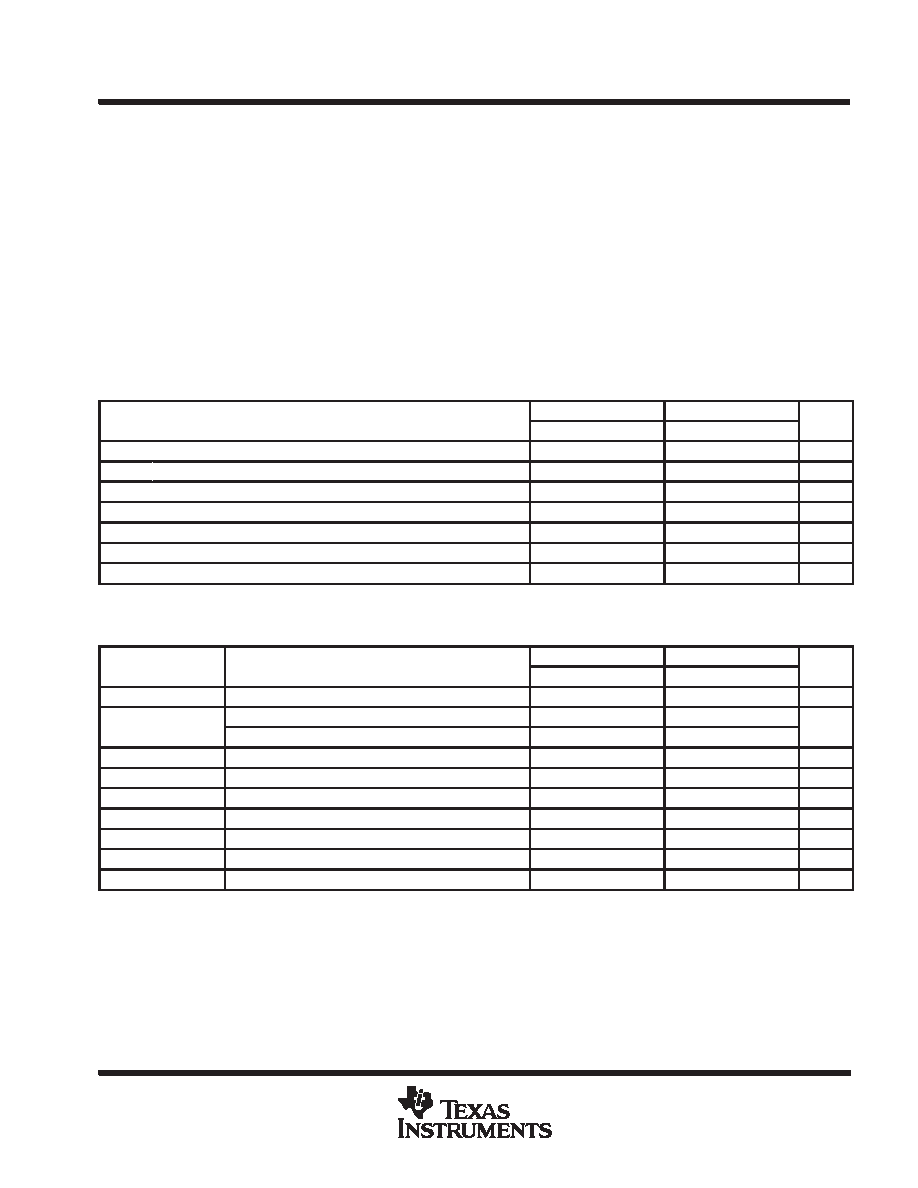
recommended operating conditions
SN54F30
SN74F30
UNIT
MIN
NOM
MAX
MIN
NOM
MAX
UNIT
VCC
Supply voltage
4.5
5
5.5
4.5
5
5.5
V
VIH
High-level input voltage
2
V
VIL
Low-level input voltage
0.8
V
IIK
Input clamp current
–18
mA
IOH
High-level output current
–1
mA
IOL
Low-level output current
20
mA
TA
Operating free-air temperature
–55
125
0
70
°C
electrical characteristics over recommended operating free-air temperature range (unless
otherwise noted)
PARAMETER
TEST CONDITIONS
SN54F30
SN74F30
UNIT
PARAMETER
TEST CONDITIONS
MIN
TYP
MAX
MIN
TYP
MAX
UNIT
VIK
VCC = 4.5 V,
II = – 18 mA
– 1.2
V
VOH
VCC = 4.5 V,
IOH = – 1 mA
2.5
3.4
2.5
3.4
V
VOH
VCC = 4.75 V,
IOH = – 1 mA
2.7
V
VOL
VCC = 4.5 V,
IOL = 20 mA
0.3
0.5
0.3
0.5
V
II
VCC = 5.5 V,
VI = 7 V
0.1
mA
IIH
VCC = 5.5 V,
VI = 2.7 V
20
A
IIL
VCC = 5.5 V,
VI = 0.5 V
– 0.6
mA
IOS§
VCC = 5.5 V,
VO = 0
–60
–150
–60
–150
mA
ICCH
VCC = 5.5 V,
VI = 0
0.7
1.5
0.7
1.5
mA
ICCL
VCC = 5.5 V,
VI = 4.5 V
2.2
4
2.2
4
mA
All typical values are at VCC = 5 V, TA = 25°C.
§ Not more than one output should be shorted at a time, and the duration of the short circuit should not exceed one second.
相关PDF资料 |
PDF描述 |
|---|---|
| SNJ54F74FK | F/FAST SERIES, DUAL POSITIVE EDGE TRIGGERED D FLIP-FLOP, COMPLEMENTARY OUTPUT, CQCC20 |
| SNJ54HC02WR | HC/UH SERIES, QUAD 2-INPUT NOR GATE, CDFP14 |
| SNJ54HC04J | HC/UH SERIES, HEX 1-INPUT INVERT GATE, CDIP14 |
| SN74HC04DRE4 | HC/UH SERIES, HEX 1-INPUT INVERT GATE, PDSO14 |
| SNJ54HC05WR | HC/UH SERIES, HEX 1-INPUT INVERT GATE, CDFP14 |
相关代理商/技术参数 |
参数描述 |
|---|---|
| SN54F32J | 制造商:Texas Instruments 功能描述:OR Gate 4-Element 2-IN Bipolar 14-Pin CDIP Tube 制造商:Rochester Electronics LLC 功能描述:- Bulk 制造商:Texas Instruments 功能描述:QUAD 2-INPUT OR GATE - Rail/Tube |
| SN54F373J | 制造商:Texas Instruments 功能描述:Latch Transparent 3-ST 8-CH D-Type 20-Pin CDIP Tube 制造商:Rochester Electronics LLC 功能描述:- Bulk |
| SN54F374J | 制造商:Texas Instruments 功能描述:Flip Flop D-Type Bus Interface Pos-Edge 3-ST 1-Element 20-Pin CDIP Tube 制造商:Rochester Electronics LLC 功能描述:- Bulk |
| SN54F518J | 制造商:Rochester Electronics LLC 功能描述:- Bulk |
| SN54F521J | 制造商:Rochester Electronics LLC 功能描述: 制造商:Texas Instruments 功能描述: 制造商:Texas Instruments 功能描述:Identity Comparator 8-Bit 20-Pin CDIP Tube |
发布紧急采购,3分钟左右您将得到回复。