- 您现在的位置:买卖IC网 > PDF目录384928 > SPM32-CA (Fairchild Semiconductor Corporation) SPMTM (Smart Power Module) PDF资料下载
参数资料
| 型号: | SPM32-CA |
| 厂商: | Fairchild Semiconductor Corporation |
| 英文描述: | SPMTM (Smart Power Module) |
| 中文描述: | SPMTM(智能功率模块) |
| 文件页数: | 14/16页 |
| 文件大小: | 428K |
| 代理商: | SPM32-CA |
2006 Fairchild Semiconductor Corporation
F
April 3, 2006
Note:
1) R
C
/R
C
PH
/R
PF
C
PF
coupling at each SPM input is recommended in order to prevent input signals’ oscillation and it should be as close as possible to each
SPM input pin.
2) By virtue of integrating an application specific type HVIC inside the SPM, direct coupling to CPU terminals without any opto-coupler or transformer isolation is
possible.
3) V
output is open collector type. This signal line should be pulled up to the positive side of the 5V power supply with approximately 4.7k
resistance. Please
refer to Fig. 12.
4) C
SP15
of around 7 times larger than bootstrap capacitor C
is recommended.
5) V
FO
output pulse width should be determined by connecting an external capacitor(C
FOD
) between C
FOD
(pin8) and COM
(L)
(pin2). (Example : if C
FOD
= 33 nF, then
t
= 1.8 ms (typ.)) Please refer to the note 6 for calculation method.
6) Each input signal line should be pulled up to the 5V power supply with approximately 4.7k
(at high side input) or 2k
(
at low side input) resistance (other RC
coupling circuits at each input may be needed depending on the PWM control scheme used and on the wiring impedance of the system’s printed circuit board).
Approximately a 0.22~2nF by-pass capacitor should be used across each power supply connection terminals.
7) To prevent errors of the protection function, the wiring around R
, R
and C
should be as short as possible.
8) In the short-circuit protection circuit, please select the R
C
time constant in the range 3~4
μ
s.
9) Each capacitor should be mounted as close to the pins of the SPM as possible.
10)To prevent surge destruction, the wiring between the smoothing capacitor and the P&N pins should be as short as possible. The use of a high frequency non-
inductive capacitor of around 0.1~0.22
μ
F between the P&N pins is recommended.
11)Relays are used at almost every systems of electrical equipments of home appliances. In these cases, there should be sufficient distance between the CPU and
the relays. It is recommended that the distance be 5cm at least.
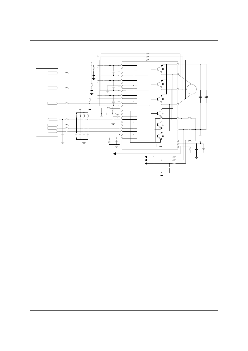
Fig. 14. Application Circuit
COM(L)
VCC
IN(UL)
IN(VL)
IN(WL)
VFO
C(FOD)
C(SC)
OUT(UL)
OUT(VL)
OUT(WL)
N
U
(26)
N
V
(27)
N
W
(28)
U (29)
V (30)
W (31)
P (32)
(23) V
S(W)
(22) V
B(W)
(21) V
CC(WH)
(19) V
S(V)
(18) V
B(V)
(17) V
CC(VH)
(9) C
SC
(8) C
FOD
(7) V
FO
(6) COM
(L)
(5) IN
(WL)
(4) IN
(VL)
(3) IN
(UL)
(2) COM
(L)
(1) V
CC(L)
(10) R
SC
V
TH
(24)
R
TH
(25)
VCC
COM
IN
VB
OUT
VS
VB
VCC
VS
OUT
IN
COM
VCC
COM
IN
VB
OUT
VS
(20) IN
(WH)
(15) IN
(VH)
(16) COM
(H)
(14) V
S(U)
(13) V
B(U)
(12) V
CC(UH)
(11) IN
(UH)
Fault
15V line
C
BS
C
BSC
R
BS
D
BS
C
BS
C
BSC
R
BS
D
BS
C
BS
C
BSC
R
BS
D
BS
C
SP15
C
SPC15
C
FOD
5V line
R
PF
C
PL
C
BPF
R
PL
R
PL
R
PL
C
PL
C
PL
5V line
C
PH
R
PH
C
PH
R
PH
C
PH
R
PH
R
S
R
S
R
S
R
S
R
S
R
S
R
S
M
Vdc
C
DCS
5V line
R
TH
C
SP05
C
SPC05
THERMISTOR
Temp. Monitoring
Gating UH
Gating VH
Gating WH
Gating WH
Gating VH
Gating UH
C
PF
U
C
P
R
FU
R
FV
R
FW
R
SU
R
SV
R
SW
C
FU
C
FV
C
FW
W-Phase Current
V-Phase Current
U-Phase Current
R
F
C
SC
R
SC
R
CSC
R
E(WH)
R
E(VH)
R
E(UH)
相关PDF资料 |
PDF描述 |
|---|---|
| SR107 | SCHOTTKY BARRIER RECTIFIERS(1.0A,70-100V) |
| SR108 | 1 Amp Schottky Barrier Rectifier 50 - 100 Volts |
| SR108 | SCHOTTKY BARRIER RECTIFIERS(1.0A,70-100V) |
| SR109 | SCHOTTKY BARRIER RECTIFIERS(1.0A,70-100V) |
| SR108 | 1.0 AMP. SCHOTTKY BARRIER RECTIFIERS |
相关代理商/技术参数 |
参数描述 |
|---|---|
| SPM-33A | 制造商:JDSU 制造商全称:JDS Uniphase Corporation 功能描述:Selective Level Meters |
| SPM-34A | 制造商:JDSU 制造商全称:JDS Uniphase Corporation 功能描述:Selective Level Meters |
| SPM3501 | 制造商:SANYO 制造商全称:Sanyo Semicon Device 功能描述:SPM3501 |
| SPM-35A | 制造商:JDSU 制造商全称:JDS Uniphase Corporation 功能描述:Selective Level Meters |
| SPM-3602AG | 制造商:OPTOWAY 制造商全称:Optoway Technology Inc 功能描述:1310 nm TX / 1550 nm RX , 3.3V / 125 Mbps Multi-Mode Single-Fiber SFP Transceiver |
发布紧急采购,3分钟左右您将得到回复。