- 您现在的位置:买卖IC网 > PDF目录193634 > SQL48T20033-NDABG (POWER-ONE INC) DC-DC REG PWR SUPPLY MODULE PDF资料下载
参数资料
| 型号: | SQL48T20033-NDABG |
| 厂商: | POWER-ONE INC |
| 元件分类: | 电源模块 |
| 英文描述: | DC-DC REG PWR SUPPLY MODULE |
| 封装: | ROHS COMPLIANT, ONE-EIGHTH BRICK PACKAGE-8 |
| 文件页数: | 8/14页 |
| 文件大小: | 773K |
| 代理商: | SQL48T20033-NDABG |
Rev 0.2, 3-Mar-11
www.power-one.com
Page 3 of 14
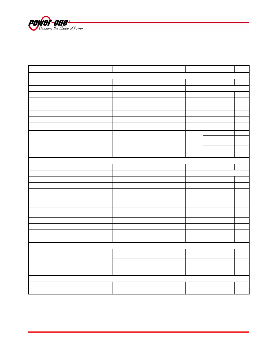
SQL48T20033 DC-DC Converter
36-75 VDC Input; 3.3 VDC @ 20A Output
Preliminary Data Sheet
Electrical Specifications (continued)
Conditions: TA = 25 C, Airflow = 300 LFM (1.5 m/s), Vin = 48 VDC, unless otherwise specified.
Parameter
Notes
Min
Typ
Max
Units
Input Characteristics
Operating Input Voltage Range
36
48
75
VDC
Input Undervoltage Lockout
Turn-on Threshold
31.5
33.5
35.5
VDC
Turn-off Threshold
30
32
34
VDC
Lockout Hysteresis Voltage
1.0
2.0
VDC
Maximum Input Current
3.3 Vout, Full Load @ 36VDC In
2.1
ADC
Input Standby Current
Vin = 48V, converter disabled
5
mADC
Input No Load Current (No load on the output)
Vin = 48V, converter enabled
45
mADC
Input Reflected-Ripple Current,
ic
Vin = 48V, 20 MHz bandwidth,
Full Load (resistive)
(See Fig. J)
200
400
mAPK-PK
150
mARMS
Input Reflected-Ripple Current,
i
S
30
mAPK-PK
5
mARMS
Input Voltage Ripple Rejection
@ 120 Hz
60
dB
Output Characteristics
Output Voltage Setpoint
VIN=48V, IOUT=0Amps, TA=25°C
3.25
3.3
3.35
VDC
Output Regulation
Over Line
IOUT=20Amps, TA=25°C
±2
±17
mV
Over Load
VIN=48V, , TA=25°C
±2
±17
mV
Output Voltage Range
Over line, load and temperature
3.2
3.4
VDC
Output Ripple and Noise
– 20 MHz bandwidth
IOUT=20Amps,
CEXT =10 F tantalum + 1 F ceramic
30
100
mVPK-PK
15
30
VRMS
External Load Capacitance
1
Plus Full Load (resistive)
CEXT
ESR
0
1
10,000
F
mOhm
Output Current Range
0
20
ADC
Current Limit Inception
Non-latching
22
26
30
ADC
Short-Circuit Current
Pk:
Non-latching Short = 10 m
30
Amps
RMS:
5
10
ARMS
Dynamic Response
Load Change 50%-75%-50% of IOUT Max
di/dt = 0.1
A/μs
CEXT = 10F tantalum + 1F ceramic
±50
mV
di/dt = 1.0
A/μs
CEXT = 470F POS + 1F ceramic
±100
mV
Settling Time to 1% of VOUT
20
s
Efficiency
@ 100% Load
48VIN, TA=25°C, 300LFM (1.5 m/s)
91
%
@ 50% Load
90
%
Additional Notes:
1
See
“Input & Output Impedance”, Page 4.
相关PDF资料 |
PDF描述 |
|---|---|
| SQL48T20033-PDBB | DC-DC REG PWR SUPPLY MODULE |
| SQM48T20012-NBAT | 1-OUTPUT 24 W DC-DC REG PWR SUPPLY MODULE |
| SQM48T20018-NAC0 | 1-OUTPUT 36 W DC-DC REG PWR SUPPLY MODULE |
| SQM48T20012-NECTG | 1-OUTPUT 24 W DC-DC REG PWR SUPPLY MODULE |
| SQM48T20012-PEA0G | 1-OUTPUT 24 W DC-DC REG PWR SUPPLY MODULE |
相关代理商/技术参数 |
参数描述 |
|---|---|
| SQL48T20033-NDB0G | 制造商:Power-One 功能描述:- Trays |
| SQL48T20033-NDBBG | 制造商:Power-One 功能描述:- Trays |
| SQLEDS-1-4-26 | 制造商:Richco 功能描述:3mm LED square spacer,SQLEDS-1-4-26 |
| SQLEDS1-4-26 | 功能描述:LED SPACER SQUARE T-1 SER 1/4" RoHS:是 类别:光电元件 >> LED - 垫片,支座 系列:SQLEDS 标准包装:1,000 系列:* |
| SQLEDS-1-6-26 | 制造商:Richco 功能描述:3mm LED square spacer,SQLEDS-1-6-26 |
发布紧急采购,3分钟左右您将得到回复。