- 您现在的位置:买卖IC网 > PDF目录219849 > SR22W 2 A, 20 V, SILICON, RECTIFIER DIODE PDF资料下载
参数资料
| 型号: | SR22W |
| 元件分类: | 参考电压二极管 |
| 英文描述: | 2 A, 20 V, SILICON, RECTIFIER DIODE |
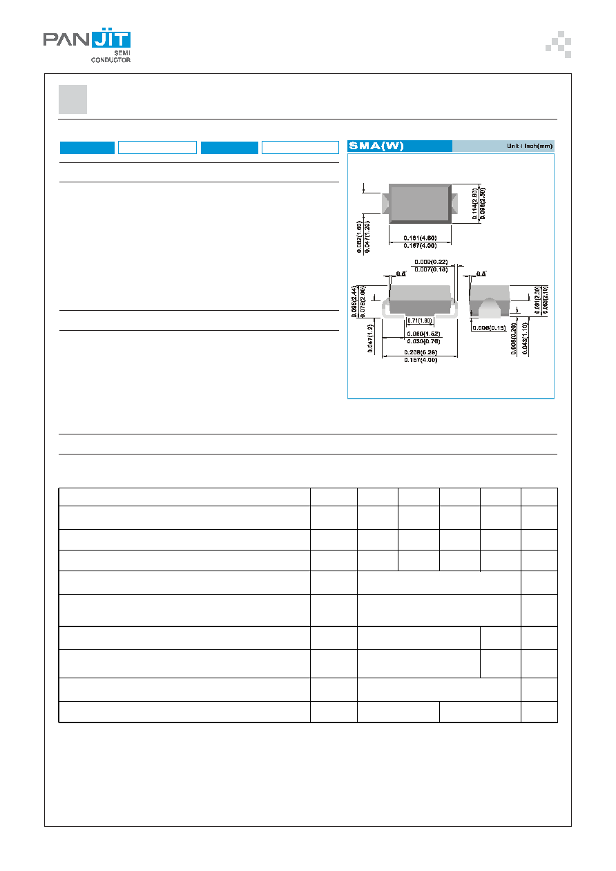
| 封装: | ROHS COMPLIANT, PLASTIC, SMA(W), 2 PIN |
| 文件页数: | 1/3页 |
| 文件大小: | 127K |
| 代理商: | SR22W |
PAGE . 1
June 7,2011-REV.03
SR22W SERIES
FEATURES
Plastic package has Underwriters Laboratory
Flammability Classification 94V-O
For surface mounted applications
Low profile package
Built-in strain relief
Metal to silicon rectifier. majority carrier conduction
Low power loss,high efficiency
High surge capacity
For use in low voltage high frequency inverters, free wheeling,
and polarity protection applications
In compliance with EU RoHS 2002/95/EC directives
MECHANICAL DATA
Case: SMA(W) molded plastic
Terminals:Solder plated, solderable per MIL-STD-750,Method 2026
Polarity: Color band denotes cathode end
Standard packaging: 12mm tape (EIA-481)
Weight: 0.002 ounce, 0.067 gram
SCHOTTKY BARRIER RECTIFIER
MAXIMUM RATINGS AND ELECTRICAL CHARACTERISTICS
Ratings at 25°C ambient temperature unless otherwise specified.
Resistive or inductive load.
NOTES:
1. Pulse Test with PW =300sec, 1% Duty Cycle.
2. Mounted on PCB 6x5mm copper pad areas.
VOLTAGE
20~60 Volts
2 Amperes
CURRENT
PA RA M E TE R
S YM B O L
S R22W
S R23W
S R24 W
S R2 6W
UNITS
Ma xi mum Re c urre nt P e a k Re ve rs e Vo l ta g e
V RRM
2 0
3 0
40
60
V
Ma xi mum RMS Vo lt a g e
V RMS
1 4
21
28
42
V
Ma xi mum D C B l o c k i ng Vo lt a g e
V DC
2 0
3 0
40
60
V
M axi m um A ver age F or war d C ur re nt ( s ee F i g. 4)
IF(AV )
2. 0
A
P eak F o r war d S urg e C ur re nt : 8. 3m s si ng le ha l f
s i ne -wave s uper i m pos ed on r at ed loa d
(J E D E C me t ho d )
IFS M
50
A
M axi m um F o r war d Vol tag e at 2. 0A ( Note 1)
V F
0. 5
0 .7
V
Ma xi mum D C Re ve rs e C urre nt a t Ra te d
DC B l o c k i ng Vo lt a g e
T
J =2 5
O C
T
J = 100
O C
IR
0. 5
20
0. 1
20
mA
Typi c a l Ther m a l Re si st ance ( No t e 2)
R
θJL
R
θJA
25
100
OC / W
O pe r ati ng Junc t i on a nd S to ra ge Te m per at ur e Range
TJ,TSTG
- 55 t o + 1 25
- 55 to + 150
O C
相关PDF资料 |
PDF描述 |
|---|---|
| SS2040HET/R7 | 2 A, 40 V, SILICON, RECTIFIER DIODE |
| SD101AWT/R13 | 0.35 A, 60 V, SILICON, SIGNAL DIODE |
| SD103AXGRKG | 0.2 A, 40 V, SILICON, SIGNAL DIODE |
| SD103BWST/R13 | 0.35 A, 30 V, SILICON, SIGNAL DIODE |
| SMFZ36V | 39.24 V, 1 W, SILICON, UNIDIRECTIONAL VOLTAGE REGULATOR DIODE |
相关代理商/技术参数 |
参数描述 |
|---|---|
| SR23 | 制造商:MPS 制造商全称:Monolithic Power Systems 功能描述:2A, 380 KHz Step-Down Converter |
| SR230 | 制造商:EDSYN 功能描述: |
| SR230-12 | 制造商:LAMBDA 制造商全称:DENSEI-LAMBDA 功能描述:Single output 20W ~ 660W |
| SR230-15 | 制造商:LAMBDA 制造商全称:DENSEI-LAMBDA 功能描述:Single output 20W ~ 660W |
| SR230-18 | 制造商:LAMBDA 制造商全称:DENSEI-LAMBDA 功能描述:Single output 20W ~ 660W |
发布紧急采购,3分钟左右您将得到回复。