- 您现在的位置:买卖IC网 > PDF目录18918 > SS-1T-4 (Omron Electronics Inc-EMC Div)SWITCH BASIC SUBMINI PIN PLUNGER PDF资料下载
参数资料
| 型号: | SS-1T-4 |
| 厂商: | Omron Electronics Inc-EMC Div |
| 文件页数: | 7/8页 |
| 文件大小: | 0K |
| 描述: | SWITCH BASIC SUBMINI PIN PLUNGER |
| 产品培训模块: | Snap Switches |
| 标准包装: | 100 |
| 系列: | SS |
| 其它名称: | SS1T4 |
�� �
�
�Precautions�
�Be� sure� to� read� the� precautions� and� information� common� to� all� Snap� Action� and� Detection� Switches,� contained� in� the� Technical� User’s� Guide,�
�“Snap� Action� Switches,� Technical� Information”� for� correct� use.�
�■� Correct� Use�
�Mounting�
�Mount� the� switch� onto� a� flat� surface.� Mounting� on� an� uneven� surface�
�may� cause� deformation� of� the� switch,� resulting� in� faulty� operation� or�
�breakage� in� the� housing.�
�Operating� Stroke�
�Take� particular� care� in� setting� the� operating� stroke� for� the� pin� plunger�
�models.� Make� sure� that� the� operating� stroke� is� 70%� to� 100%� of� the�
�rated� OT� distance.� Do� not� operate� the� actuator� exceeding� the� OT� dis-�
�tance,� otherwise� the� life� expectancy� of� the� switch� may� be� shortened.�
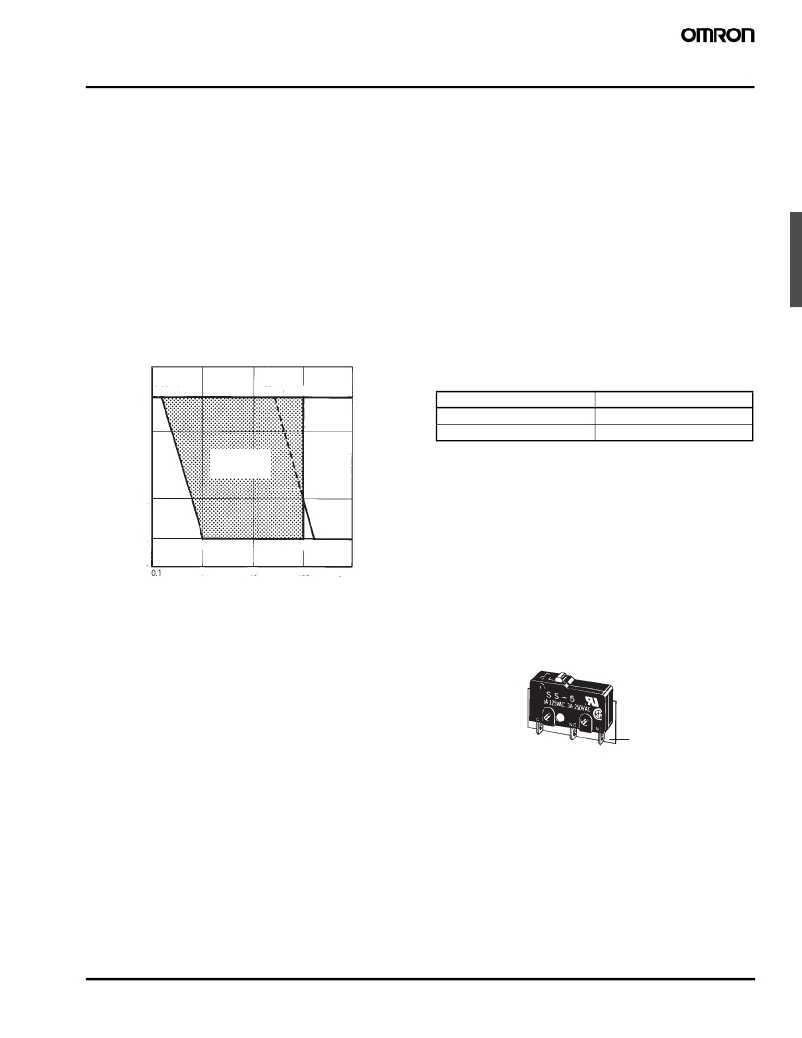
�Using� Microloads�
�Using� a� model� for� ordinary� loads� to� switch� microloads� may� result� in�
�faulty� operation.� Instead,� use� the� models� that� are� designed� for�
�microloads� and� that� operate� in� the� following� range;�
�■� Cautions�
�Handling�
�Turn� OFF� the� power� supply� before� mounting� or� removing� the� switch,�
�wiring,� or� performing� maintenance� for� inspection.� Failure� to� do� so�
�may� result� in� electric� shock� or� burning�
�Terminal� Connection�
�When� soldering� the� lead� wire� to� the� terminal,� first� insert� the� lead� wire�
�conductor� through� the� terminal� hole� and� then� solder.�
�Make� sure� that� the� capacity� of� the� soldering� iron� is� 60� W� maximum.�
�Do� not� take� more� than� 5� seconds� to� solder� the� switch� terminal.�
�Improper� soldering� involving� an� excessively� high� temperature� or�
�excessive� soldering� time� may� deteriorate� the� characteristics� of� the�
�switch.�
�Be� sure� to� apply� only� the� minimum� required� amount� of� flux.� The�
�switch� may� have� contact� failures� if� flux� intrudes� in� the� interior� of� the�
�switch.�
�Use� the� following� lead� wires� to� connect� to� the� solder� terminals;�
�30�
�0.16mA�
�26mA 100mA�
�Model�
�Conductor� size�
�SS-5�
�0.5� to� 0.75� mm� 2�
�24�
�SS-10�
�0.75� mm� 2�
�Operating� range�
�for� micro� load�
�models� SS-01�
�Operating�
�range� for�
�general-load�
�models�
�If� the� PCB� terminal� models� are� soldered� in� a� solder� bath,� flux� will� per-�
�meate� inside� the� switch� and� cause� contact� failure.� Therefore,� manu-�
�ally� solder� the� PCB� terminal.�
�12�
�5�
�Inopera� b� le�
�range�
�1mA�
�SS-5,� SS-10�
�100mA 160mA�
�Wire� the� quick-connect� terminals� (#110)� with� receptacles.� Insert� the�
�terminals� straight� into� the� receptacles.� Do� not� impose� excessive�
�force� on� the� terminal� in� the� horizontal� direction,� otherwise� the� termi-�
�nal� may� be� deformed� or� the� housing� may� be� damaged.�
�Insulation� Distance�
�0�
�1�
�10�
�100�
�1,000�
�Use� a� separator� between� the� switch� and� metal� mounting� panels,� to�
�C� u� rrent� (mA)�
�However,� even� when� using� microload� models� within� the� operating�
�range� shown� above,� if� inrush� current� or� inductive� voltage� spikes�
�occur� when� the� contact� is� opened� or� closed,� then� contact� wear� may�
�increase� and� so� decrease� the� service� life.� Therefore,� insert� a� contact�
�protection� circuit� where� necessary.�
�ensure� proper� dielectric� characteristics� are� achieved.�
�According� to� E� N� 61058-1,� the� minimum� insulation� thickness� for� this�
�switch� should� be� 1.1� mm� and� minimum� clearance� distance� between�
�the� terminal� and� mounting� plate� should� be� 1.6� mm.� If� the� insulation�
�distance� cannot� be� provided� in� the� product� incorporating� the� switch,�
�either� use� a� switch� with� insulation� barrier� or� use� a� separator� to�
�ensure� sufficient� insulation� distance.�
�Separator�
�Snap� Action� Switch�
�SS�
�101�
�相关PDF资料 |
PDF描述 |
|---|---|
| NB12KC0101MBA | THERM NTC 100OHM 20% 0805 SMD |
| SS-10GL14 | SWITCH LEVER SPDT 10A |
| D3V-16-1C25-K | SWITCH SNAP SPDT 16A QC TERM |
| E33-50H | SWITCH LEVER SPDT 10A QC TERM |
| SS-5GL07T | SWITCH 5A HINGE SPDT TAB |
相关代理商/技术参数 |
参数描述 |
|---|---|
| SS1V100KC | 制造商:DBLECTRO 制造商全称:DB Lectro Inc 功能描述:ALUMINIUM ELECTROLYTIC CAPACITOR |
| SS1V100KR | 制造商:DBLECTRO 制造商全称:DB Lectro Inc 功能描述:ALUMINIUM ELECTROLYTIC CAPACITOR |
| SS1V100KT | 制造商:DBLECTRO 制造商全称:DB Lectro Inc 功能描述:ALUMINIUM ELECTROLYTIC CAPACITOR |
| SS1V100LC | 制造商:DBLECTRO 制造商全称:DB Lectro Inc 功能描述:ALUMINIUM ELECTROLYTIC CAPACITOR |
| SS1V100LR | 制造商:DBLECTRO 制造商全称:DB Lectro Inc 功能描述:ALUMINIUM ELECTROLYTIC CAPACITOR |
发布紧急采购,3分钟左右您将得到回复。