- 您现在的位置:买卖IC网 > PDF目录10940 > SSM2603CPZ-REEL7 (Analog Devices Inc)IC CODEC AUDIO LOW POWER 28LFCSP PDF资料下载
参数资料
| 型号: | SSM2603CPZ-REEL7 |
| 厂商: | Analog Devices Inc |
| 文件页数: | 7/32页 |
| 文件大小: | 0K |
| 描述: | IC CODEC AUDIO LOW POWER 28LFCSP |
| 标准包装: | 1,500 |
| 类型: | 立体声音频 |
| 分辨率(位): | 24 b |
| ADC / DAC 数量: | 2 / 2 |
| 三角积分调变: | 无 |
| S/N 比,标准 ADC / DAC (db): | 90 / 100 |
| 电压 - 电源,模拟: | 1.8 V ~ 3.6 V |
| 电压 - 电源,数字: | 1.5 V ~ 3.6 V |
| 工作温度: | -40°C ~ 85°C |
| 安装类型: | 表面贴装 |
| 封装/外壳: | 28-VFQFN 裸露焊盘,CSP |
| 供应商设备封装: | 28-LFCSP-VQ |
| 包装: | 带卷 (TR) |
第1页第2页第3页第4页第5页第6页当前第7页第8页第9页第10页第11页第12页第13页第14页第15页第16页第17页第18页第19页第20页第21页第22页第23页第24页第25页第26页第27页第28页第29页第30页第31页第32页
Data Sheet
SSM2603
Rev. C | Page 15 of 32
DIGITAL AUDIO INTERFACE
The digital audio input can support the following four digital audio
communication protocols: right-justified mode, left-justified mode,
I2S mode, and digital signal processor (DSP) mode.
The mode selection is performed by writing to the FORMAT bits
of the digital audio interface register (Register R7, Bit D1 and
Bit D0). All modes are MSB first and operate with data of 16
to 32 bits.
Recording Mode
On the RECDAT output pin, the digital audio interface can
send digital audio data for recording mode operation. The
digital audio interface outputs the processed internal ADC
digital filter data onto the RECDAT output. The digital audio
data stream on RECDAT comprises left- and right-channel
audio data that is time domain multiplexed.
The RECLRC is the digital audio frame clock signal that separates
left- and right-channel data on the RECDAT lines.
The BCLK signal acts as the digital audio clock. Depending on
if the SSM2603 is in master or slave mode, the BCLK signal is
either an input or an output signal. During a recording operation,
RECDAT and RECLRC must be synchronous to the BCLK signal
to avoid data corruption.
Playback Mode
On the PBDAT input pin, the digital audio interface can receive
digital audio data for playback mode operation. The digital audio
data stream on PBDAT comprises left- and right-channel audio
data that is time domain multiplexed. The PBLRC is the digital
audio frame clock signal that separates left- and right-channel
data on the PBDAT lines.
The BCLK signal acts as the digital audio clock. Depending on
whether the SSM2603 is in master or slave mode, the BCLK
signal is either an input or an output signal. During a playback
operation, PBDAT and PBLRC must be synchronous to the
BCLK signal to avoid data corruption.
Digital Audio Data Sampling Rate
To accommodate a wide variety of commonly used DAC and
ADC sampling rates, the SSM2603 allows for two modes of
operation, normal and USB, selected by the USB bit (Register R8,
Bit D0).
In normal mode, the SSM2603 supports digital audio sampling
rates from 8 kHz to 96 kHz. Normal mode supports 256 fS and
384 fS based clocks. To select the desired sampling rate, the user
must set the appropriate sampling rate register in the SR control bits
(Register R8, Bit D2 to Bit D5) and match this selection to the
core clock frequency that is pulsed on the MCLK pin. See Table 29
and Table 30 for guidelines.
In USB mode, the SSM2603 supports digital audio sampling rates
from 8 kHz to 96 kHz. USB mode supports 250 fS and 272 fS
based clocks. USB mode is enabled on the SSM2603 to support
the common universal serial bus (USB) clock rate of 12 MHz,
or to support 24 MHz if the CLKDIV2 control register bit is
activated. The user must set the appropriate sampling rate in
the SR control bits (Register R8, Bit D2 to Bit D5). See Table 29
and Table 31 for guidelines.
Note that the sampling rate is generated as a fixed divider from
the MCLK signal. Because all audio processing references the
core MCLK signal, corruption of this signal, in turn, corrupts
the outgoing audio quality of the SSM2603. The BCLK/RECLRC/
RECDAT or BCLK/PBLRC/PBDAT signals must be synchronized
with MCLK in the digital audio interface circuit. MCLK must
be faster or equal to the BCLK frequency to guarantee that no
data is lost during data synchronization.
The BCLK frequency should be greater than
Sampling Rate × Word Length × 2
Ensuring that the BCLK frequency is greater than this value
guarantees that all valid data bits are captured by the digital audio
interface circuitry. For example, if a 32 kHz digital audio sampling
rate with a 32-bit word length is desired, BCLK ≥ 2.048 MHz.
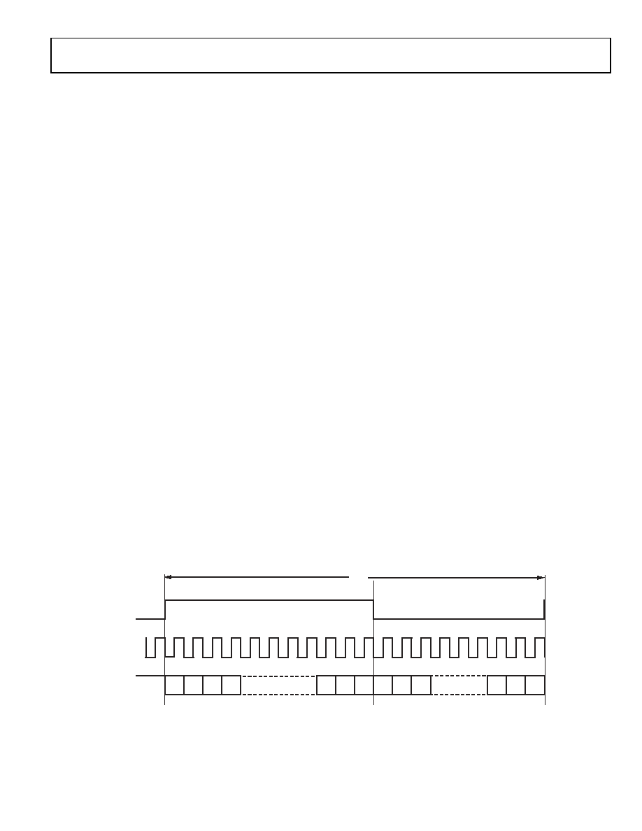
Figure 23. Left-Justified Audio Input Mode
07241-
013
RECLRC/
PBLRC
BCLK
RECDAT/
PBDAT
1
2
3
4
N
X
N
1
2
LEFT CHANNEL
3
RIGHT CHANNEL
1/
fS
X = DON’T CARE.
相关PDF资料 |
PDF描述 |
|---|---|
| VI-J3V-IX-S | CONVERTER MOD DC/DC 5.8V 75W |
| SSM2603CPZ-REEL | IC CODEC AUDIO LOW POWER 28LFCSP |
| VI-B21-IW-B1 | CONVERTER MOD DC/DC 12V 100W |
| CS42L55-CNZR | IC CODEC STER H-HDPN AMP 36-QFN |
| DSP56F807VF80 | IC DSP 80MHZ 60K FLASH 160-BGA |
相关代理商/技术参数 |
参数描述 |
|---|---|
| SSM2603-EVALZ | 功能描述:BOARD EVALUATION FOR SSM2603 RoHS:是 类别:编程器,开发系统 >> 评估演示板和套件 系列:- 标准包装:1 系列:- 主要目的:电信,线路接口单元(LIU) 嵌入式:- 已用 IC / 零件:IDT82V2081 主要属性:T1/J1/E1 LIU 次要属性:- 已供物品:板,电源,线缆,CD 其它名称:82EBV2081 |
| SSM2603GY | 制造商:SSC 制造商全称:Silicon Standard Corp. 功能描述:P-CHANNEL ENHANCEMENT MODE POWER MOSFET |
| SSM2604 | 制造商:AD 制造商全称:Analog Devices 功能描述:Low Power Audio Codec |
| SSM2604CPZ-R2 | 制造商:Rochester Electronics LLC 功能描述: 制造商:Analog Devices 功能描述: |
| SSM2604CPZ-REEL | 功能描述:IC AUDIO CODEC LP 20-LFCSP RoHS:是 类别:集成电路 (IC) >> 接口 - 编解码器 系列:- 标准包装:2,500 系列:- 类型:立体声音频 数据接口:串行 分辨率(位):18 b ADC / DAC 数量:2 / 2 三角积分调变:是 S/N 比,标准 ADC / DAC (db):81.5 / 88 动态范围,标准 ADC / DAC (db):82 / 87.5 电压 - 电源,模拟:2.6 V ~ 3.3 V 电压 - 电源,数字:1.7 V ~ 3.3 V 工作温度:-40°C ~ 85°C 安装类型:表面贴装 封装/外壳:48-WFQFN 裸露焊盘 供应商设备封装:48-TQFN-EP(7x7) 包装:带卷 (TR) |
发布紧急采购,3分钟左右您将得到回复。