- 您现在的位置:买卖IC网 > PDF目录85322 > SSR-240A50R TRIGGER OUTPUT SOLID STATE RELAY, 4000 V ISOLATION-MAX PDF资料下载
参数资料
| 型号: | SSR-240A50R |
| 元件分类: | 继电器,输入/输出模块 |
| 英文描述: | TRIGGER OUTPUT SOLID STATE RELAY, 4000 V ISOLATION-MAX |
| 封装: | PLASTIC PACKAGE-4 |
| 文件页数: | 2/2页 |
| 文件大小: | 126K |
| 代理商: | SSR-240A50R |
1105
P&B
Dimensions are shown for
reference purposes only.
Dimensions are in inches over
(millimeters) unless otherwise
specified.
Catalog 1308242
Issued 3-03 (PDF Rev. 1-05)
Specifications and availability
subject to change.
www.tycoelectronics.com
Technical support:
Refer to inside back cover.
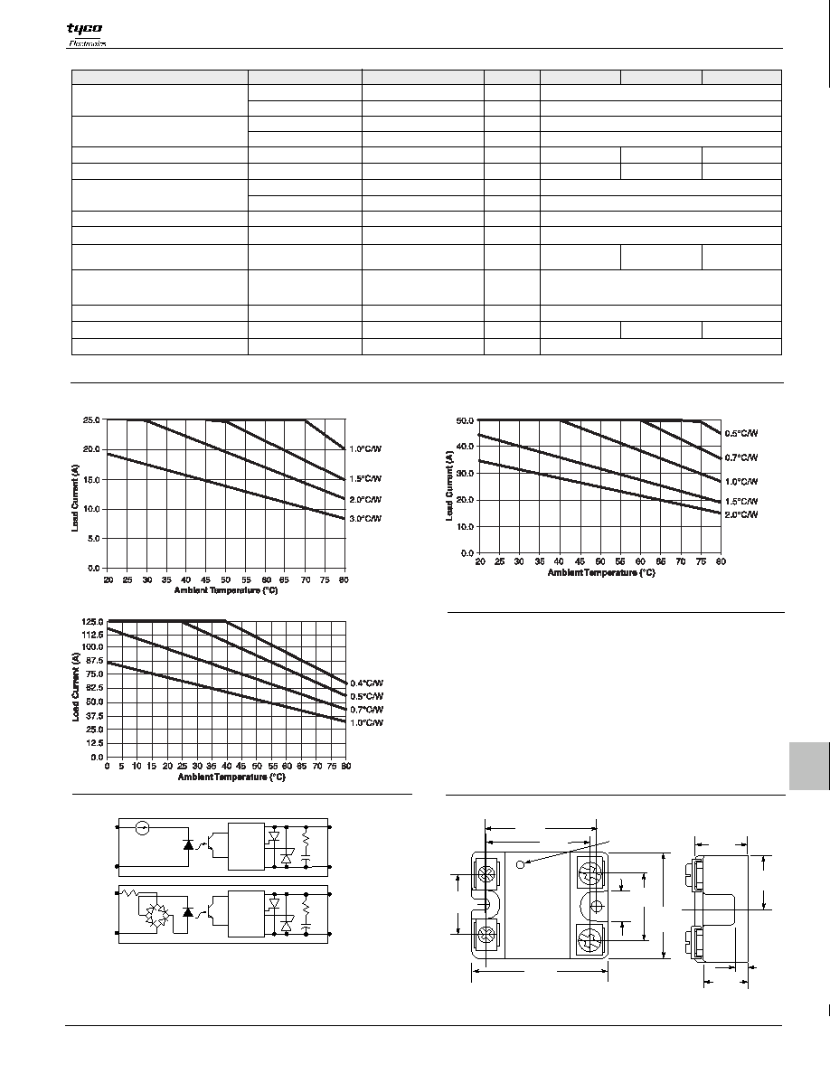
Electrical Characteristics (Thermal Derating Curves)
Output Specifications (@ 25° C, unless otherwise specified)
*See Derating Curves
Parameter
Conditions
Units
Load Voltage Range V
Repetitive Blocking Voltage (Min.)
Thermal Resistance, Junction to Case
(R
) (Max.)
I T Rating
A Sec.
V rms
°C/W
V/
s
ms
Turn-Off Time (Max.)
I = Max.
θ
2
Turn-On Time (Max.)
L
.1
25A Models
Single Cycle Surge Current (Min.)
Load Current Range I *
Leakage Current (Off-State) (Max.)
Static dv/dt (Off-State) (Min.)
Load Power Factor Rating
L
t = 8.3 ms
2
f = 60 Hz.
I = Max.
L
f = 60 Hz. V = 240V rms
V peak
V rms
A peak
On-State Voltage Drop (Max.)
250
.05 - 25
.1 - 125
J-C
1,700
.15
24 - 280
1.35
.25
48 - 660
±600
500
L
50A Models
12,000
Nom. Line Voltage
120/240V Model
480V Model
120/240 Model
480V Model
120/240 & 480V Models
120/240V Model
480V Model
120/240 & 480V Models
f = 60 Hz. V = 480V rms
L
A rms
0.4
937
.1 - 50
750
0.25
2,458
V peak
±1200
8.3 for Zero Voltage Turn-On DC input types,
20 for Zero Voltage Turn-On AC input types,
0.02 for Random Voltage Turn-On Models
8.3 for DC input types, 30 for AC input types
0.5 - 1.0
125A Models
Resistive
mA rms
Heatsink Recommendations
We recommend that solid state relay modules be mounted to a
heatsink sufficient to maintain the module’s base temperature at less
than 85°C under worst case ambient temperature and load conditions.
The heatsink mounting surface should be a smooth (30-40 micro-inch
finish), flat (30-40 micro-inch flatness across mating area), un-painted
surface which is clean and free of oxidation.
An even coating of thermal compound (Dow Corning DC340 or
equivalent) should be applied to both the heatsink and module mounting
surfaces and spread to a uniform depth of .002” to eliminate all air
pockets.
The module should be mounted to the heatsink using two #10 screws.
Outline Dimensions
1.750
(44.45)
.785
(19.94)
.250
(6.35)
1.100
(27.94)
.470
(11.9)
2.250
(57.15)
1.850
(47.0)
1.700
(43.18)
1.000
(25.4)
.875
(22.23)
.870
(22.1)
LED INDICATOR
ZERO
VOLTAGE
CIRCUIT
ZERO
VOLTAGE
CIRCUIT
1
1
2
-4
4
3
+3
EQUIVALENT CIRCUIT ONLY
CONSTANT
CURRENT
DC INPUT
OUTPUT
AC INPUT
OUTPUT
EQUIVALENT CIRCUIT ONLY
Random Turn-on Units have a Random Turn-on circuit
instead of Zero Voltage Circuit
Operating Diagrams
50A Units
25A Units
125A Units
相关PDF资料 |
PDF描述 |
|---|---|
| SSH24D50 | TRIGGER OUTPUT SOLID STATE RELAY, 4000 V ISOLATION-MAX |
| SLR-325MGT31L | T-1 SINGLE COLOR LED, YELLOWISH GREEN, 3 mm |
| SEC1503C | SINGLE COLOR LED, PURE GREEN, 2 mm |
| SECU1E01C | SINGLE COLOR LED, ULTRA HIGH INTENSITY BLUE, 2 mm |
| SEL2210W | T-1 SINGLE COLOR LED, RED, 3 mm |
相关代理商/技术参数 |
参数描述 |
|---|---|
| SSR-240A80 | 制造商:TE Connectivity 功能描述: |
| SSR240D110 | 制造商:未知厂家 制造商全称:未知厂家 功能描述: |
| SSR-240D110R | 制造商:TE Connectivity 功能描述: |
| SSR-240D125 | 功能描述:固态继电器-工业安装 RELAY SSR 240VAC 2A MINI-SIP RoHS:否 制造商:Crydom 控制电压范围:4 VDC to 32 VDC 负载电压额定值:7 VDC to 72 VDC 负载电流额定值:160 A 触点形式: 输出设备:SSR 安装风格:Panel |
| SSR240D25 | 制造商:未知厂家 制造商全称:未知厂家 功能描述: |
发布紧急采购,3分钟左右您将得到回复。