- 您现在的位置:买卖IC网 > PDF目录85210 > SSRM-600D45 TRIGGER OUTPUT SOLID STATE RELAY, 4000 V ISOLATION-MAX PDF资料下载
参数资料
| 型号: | SSRM-600D45 |
| 元件分类: | 继电器,输入/输出模块 |
| 英文描述: | TRIGGER OUTPUT SOLID STATE RELAY, 4000 V ISOLATION-MAX |
| 文件页数: | 2/2页 |
| 文件大小: | 370K |
| 代理商: | SSRM-600D45 |
2
SSRM Series Solid State Relays
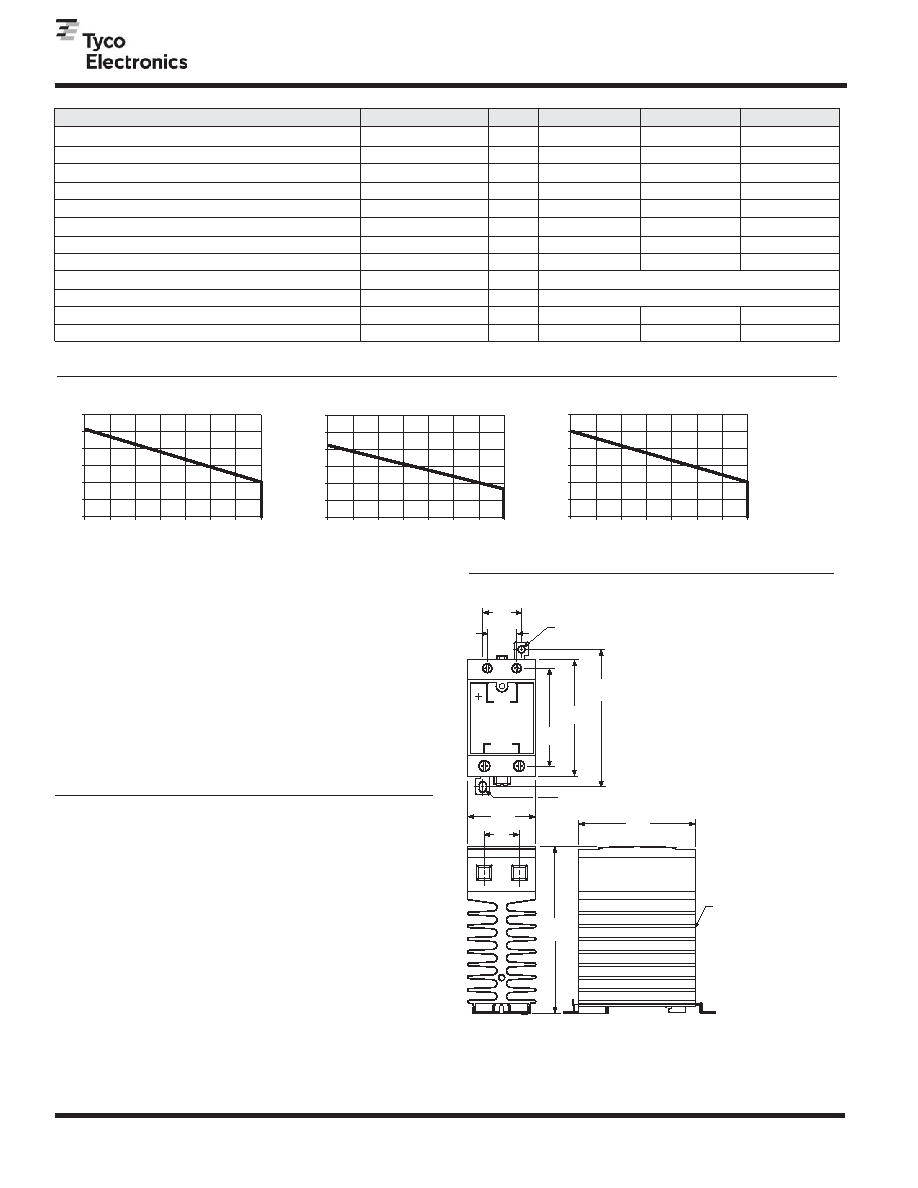
Dimensions are in inches over
(millimeters) unless otherwise
specified.
Dimensions are shown for reference
purposes only. Specifications and
availability subject to change.
South America: 55-11-2103-6000
Hong Kong: 852-2735-1628
Japan: 81-44-844-8013
UK: 44-8706-080208
USA: 1-800-522-6752
Canada: 1-905-470-4425
Mexico: 01-800-733-8926
C. America: 52-55-1106-0803
3.0
(76.2)
2.5
(63.5)
3.0
(76.2)
3.5
(88.9)
4.3
(109.2)
.9
(22.9)
1.75
(44.5)
0.75
(19.1)
1.0
(25.4)
OUTPUT
INPUT
IN
P
U
T STAT
U
S
MOUNTING HOLE
0.17 (4.3) DIA.
BLACK
ANODIZED
ALUMINUM
HEATSINK
MOUNTING SLOT
0.17 x 0.20 (4.3 x 5.1)
Outline Dimensions
Electrical Characteristics (Thermal Derating Curves)
*See Thermal Derating Curves.
Parameter
Conditions
Units
45A Rated Units
65A Rated Units
Load Voltage Range V
Repetitive Blocking Voltage (Min.)
I t Rating (Max.)
A Sec.
V rms
V/s
ms
Turn-Off Time (Max.)
I = Max.
2
Turn-On Time (Max.)
L
48 - 660
Single Cycle Surge Current (Min.)
Load Current Range I *
Leakage Current (Off-State) (Max.)
Static dv/dt (Off-State) (Min.)
Load Power Factor Rating (Min.)
L
t = 8.3 ms
2
f = 60 Hz.
f = 47 - 63 Hz.
f = 60 Hz.
I = Max.
L
f = 60 Hz. V = 600Vrms
V peak
A rms
A peak
mA rms
On-State Voltage Drop (Max.)
V peak
1,200
0.25 - 65.0
±1200
6,000
1.0
1.7
500
L
0.5
55A Rated Units
48 - 660
1,000
0.25 - 55.0
±1200
4,150
1.0
1.7
500
0.5
48 - 660
8.3 for DC Input Models, 10.0 for AC Input Models
8.3 for DC Input Models, 40.0 for AC Input Models
625
0.15 - 45.0
±1200
1,620
1.0
Thermal Resistance Junction to Case R
(Max.)
°C/W
0.28
0.31
0.63
1.7
500
0.5
V = Max.
L
θ J–C
Output Specifications (@ 25° C, unless otherwise specified)
40
30
50
60
20
10
Ambient Temperature (C)
Output
Current
(Arms)
45 A
60
45
75
90
30
15
Ambient Temperature (C)
Output
Current
(Arms)
55 A
60
45
75
90
30
15
Ambient Temperature (C)
Output
Current
(Arms)
65 A
50
60
70
80
20
30
40
10
50
60
70
80
20
30
40
10
50
60
70
80
20
30
40
10
Disclaimer
While Tyco Electronics has made every reasonable effort to ensure the
accuracy of the information in this document, Tyco Electronics does not
guarantee that it is error-free, nor does Tyco Electronics make any other
representation, warranty or guarantee that the information is accurate,
correct, reliable or current.
Tyco Electronics reserves the right to make any adjustments to the
information contained herein at any time without notice. Tyco Electronics
expressly disclaims all implied warranties regarding the information
contained herein, including, but not limited to, any implied warranties of
merchantability or fitness for a particular purpose.
The dimensions in this catalog are for reference purposes only and are
subject to change without notice. Specifications are subject to change
without notice. Consult Tyco Electronics for the latest dimensions and
design specifications.
Recommended Torque Range for Terminal Screws:
Control: 5 - 6 in lb (0.6 - 0.7 Nm).
Output: 10 - 15 in lb (1.1 - 1.7 Nm).
Catalog 8-1773454-5
Issued 4-09
www.tycoelectronics.com
2009 by Tyco Electronics Corporation. All Rights Reserved.
TE logo and Tyco Electronics are trademarks.
相关PDF资料 |
PDF描述 |
|---|---|
| SFH615A-1G | 1 CHANNEL TRANSISTOR OUTPUT OPTOCOUPLER |
| SFH6756T-X001 | 2 CHANNEL LOGIC OUTPUT OPTOCOUPLER, 10 Mbps |
| SFH6757T-X001 | 2 CHANNEL LOGIC OUTPUT OPTOCOUPLER, 10 Mbps |
| SFH6139 | 1 CHANNEL LOGIC OUTPUT OPTOCOUPLER, 0.1 Mbps |
| S-879-N11 | 3.175 mm SLOT WIDTH, 1 CHANNEL SLOTTED OPTICAL SWITCH TRANSISTOR OUTPUT |
相关代理商/技术参数 |
参数描述 |
|---|---|
| SSRM-600D55 | 功能描述:固态继电器-工业安装 SPST-NO 55A 4-32VDC RoHS:否 制造商:Crydom 控制电压范围:4 VDC to 32 VDC 负载电压额定值:7 VDC to 72 VDC 负载电流额定值:160 A 触点形式: 输出设备:SSR 安装风格:Panel |
| SSRM-600D65 | 功能描述:固态继电器-工业安装 SPST-NO 4-32VDC 65A SS RELAY RoHS:否 制造商:Crydom 控制电压范围:4 VDC to 32 VDC 负载电压额定值:7 VDC to 72 VDC 负载电流额定值:160 A 触点形式: 输出设备:SSR 安装风格:Panel |
| SSRP105 | 制造商:未知厂家 制造商全称:未知厂家 功能描述:DUAL ASYMMETRICAL OVERVOLTAGE PROTECTION FOR TELECOM LINE |
| SSRP105B1 | 功能描述:TVS二极管阵列 Overvolt Protection RoHS:否 制造商:Littelfuse 极性: 通道:4 Channels 击穿电压: 钳位电压:11.5 V 工作电压:2.5 V 峰值浪涌电流:20 A 安装风格:SMD/SMT 端接类型:SMD/SMT 系列: 最小工作温度:- 40 C 最大工作温度:+ 85 C |
| SSRP105B1RL | 功能描述:TVS二极管阵列 Overvolt Protection RoHS:否 制造商:Littelfuse 极性: 通道:4 Channels 击穿电压: 钳位电压:11.5 V 工作电压:2.5 V 峰值浪涌电流:20 A 安装风格:SMD/SMT 端接类型:SMD/SMT 系列: 最小工作温度:- 40 C 最大工作温度:+ 85 C |
发布紧急采购,3分钟左右您将得到回复。