- 您现在的位置:买卖IC网 > PDF目录299932 > ST1230C16K3P (VISHAY INTERTECHNOLOGY INC) 3200 A, 1600 V, SCR PDF资料下载
参数资料
| 型号: | ST1230C16K3P |
| 厂商: | VISHAY INTERTECHNOLOGY INC |
| 元件分类: | 晶闸管 |
| 英文描述: | 3200 A, 1600 V, SCR |
| 封装: | ROHS COMPLIANT, METAL, CASE A-24, K-PUK-2 |
| 文件页数: | 2/7页 |
| 文件大小: | 99K |
| 代理商: | ST1230C16K3P |
www.vishay.com
For technical questions, contact: ind-modules@vishay.com
Document Number: 94395
2
Revision: 11-Aug-08
ST1230C..KP Series
Vishay High Power Products
Phase Control Thyristors
(Hockey PUK Version), 1745 A
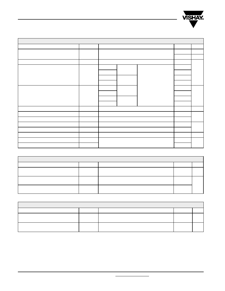
ABSOLUTE MAXIMUM RATINGS
PARAMETER
SYMBOL
TEST CONDITIONS
VALUES
UNITS
Maximum average on-state current
at heatsink temperature
IT(AV)
180° conduction, half sine wave
double side (single side) cooled
1745 (700)
A
55 (85)
°C
Maximum RMS on-state current
IT(RMS)
DC at 25 °C heatsink temperature double side cooled
3200
A
Maximum peak, one-cycle
non-repetitive surge current
ITSM
t = 10 ms
No voltage
reapplied
Sinusoidal half wave,
initial TJ = TJ maximum
33 500
t = 8.3 ms
35 100
t = 10 ms
100 % VRRM
reapplied
28 200
t = 8.3 ms
29 500
Maximum I2t for fusing
I2t
t = 10 ms
No voltage
reapplied
5615
kA2s
t = 8.3 ms
5126
t = 10 ms
100 % VRRM
reapplied
3971
t = 8.3 ms
3625
Maximum I2
√t for fusing
I2
√t
t = 0.1 to 10 ms, no voltage reapplied
56 150
kA2
√s
Low level value of threshold voltage
VT(TO)1
(16.7 % x
π x I
T(AV) < I < π x IT(AV)), TJ = TJ maximum
0.93
V
High level value of threshold voltage
VT(TO)2
(I >
π x I
T(AV)), TJ = TJ maximum
1.02
Low level value of on-state slope resistance
rt1
(16.7 % x
π x I
T(AV) < I < π x IT(AV)), TJ = TJ maximum
0.17
m
Ω
High level value of on-state slope resistance
rt2
(I >
π x I
T(AV)), TJ = TJ maximum
0.16
Maximum on-state voltage
VTM
Ipk = 4000 A, TJ = TJ maximum, tp = 10 ms sine pulse
1.62
V
Maximum holding current
IH
TJ = 25 °C, anode supply 12 V resistive load
600
mA
Typical latching current
IL
1000
SWITCHING
PARAMETER
SYMBOL
TEST CONDITIONS
VALUES
UNITS
Maximum non-repetitive rate of
rise of turned-on current
dI/dt
Gate drive 20 V, 20
Ω, t
r ≤ 1 s
TJ = TJ maximum, anode voltage ≤ 80 % VDRM
1000
A/s
Typical delay time
td
Gate current 1 A, dIg/dt = 1 A/s
Vd = 0.67 % VDRM, TJ = 25 °C
1.9
s
Typical turn-off time
tq
ITM = 550 A, TJ = TJ maximum, dI/dt = 40 A/s,
VR = 50 V, dV/dt = 20 V/s, gate 0 V 100 Ω, tp = 500 s
200
BLOCKING
PARAMETER
SYMBOL
TEST CONDITIONS
VALUES
UNITS
Maximum critical rate of rise of
off-state voltage
dV/dt
TJ = TJ maximum linear to 80 % rated VDRM
500
V/s
Maximum peak reverse and
off-state leakage current
IRRM,
IDRM
TJ = TJ maximum, rated VDRM/VRRM applied
100
mA
相关PDF资料 |
PDF描述 |
|---|---|
| ST13005N | 4 A, 400 V, NPN, Si, POWER TRANSISTOR, TO-220AB |
| ST1317BAB-32.000(T) | VCXO, CLOCK, 32 MHz, CMOS OUTPUT |
| ST16C1450CP28 | 1 CHANNEL(S), 448K bps, SERIAL COMM CONTROLLER, PDIP28 |
| ST16C1451CJ28 | 1 CHANNEL(S), 448K bps, SERIAL COMM CONTROLLER, PQCC28 |
| ST16C1550CJ28 | 1 CHANNEL(S), 448K bps, SERIAL COMM CONTROLLER, PQCC28 |
相关代理商/技术参数 |
参数描述 |
|---|---|
| ST1230C16KO | 制造商:n/a 功能描述:SCR |
| ST-1239A | 制造商:LG Corporation 功能描述:HDD 3.5" 200MB, 15MS |
| ST123D00 | 功能描述:拨动开关 TOGGLE RoHS:否 制造商:C&K Components 触点形式:DPDT 开关功能:ON - ON - ON 电流额定值: 电压额定值 AC:20 V 电压额定值 DC:20 V 功率额定值:0.4 VA 端接类型:V-Bracket 安装风格: 端子密封:Epoxy 触点电镀:Gold 照明:Not Illuminated |
| ST124 | 制造商:Aim & Thurlby Thandar Instruments 功能描述:POWER METER USB 12.4GHZ |
| ST-12405001 | 制造商:Tj Electric Appliances 功能描述:TERM.ENCL L150XW150XH80 |
发布紧急采购,3分钟左右您将得到回复。