- 您现在的位置:买卖IC网 > PDF目录195867 > ST1280C06K1LPBF 4150 A, 600 V, SCR PDF资料下载
参数资料
| 型号: | ST1280C06K1LPBF |
| 元件分类: | 晶闸管 |
| 英文描述: | 4150 A, 600 V, SCR |
| 封装: | KPUK-2 |
| 文件页数: | 3/7页 |
| 文件大小: | 87K |
| 代理商: | ST1280C06K1LPBF |
ST1280C..K Series
3
www.irf.com
Bulletin I25195 rev. B 02/00
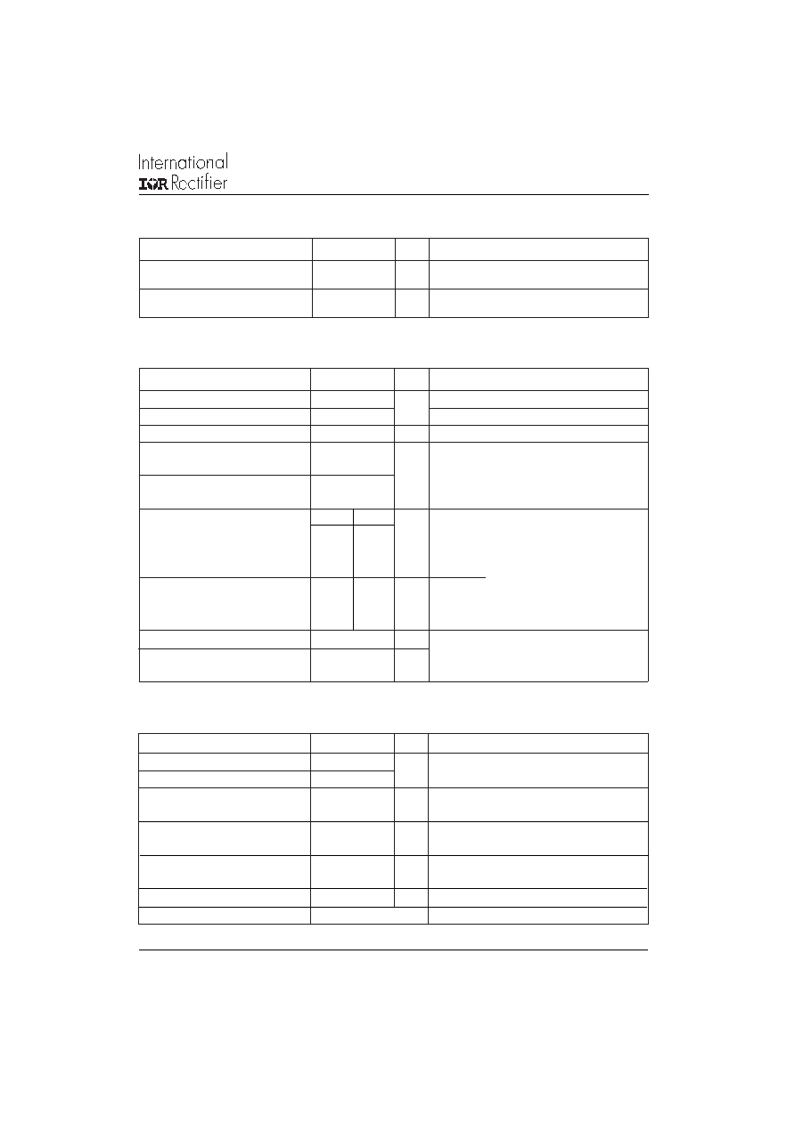
dv/dt
Maximum critical rate of rise of
off-state voltage
I
RRM
Max. peak reverse and off-state
I
DRM
leakage current
Blocking
500
V/s
T
J = TJ max. linear to 80% rated V DRM
Parameter
ST1280C..K
Units Conditions
100
mA
T
J
= T
J
max, rated V
DRM
/V
RRM
applied
P
GM
Maximum peak gate power
16
T
J
= T
J
max, t
p ≤
5ms
P
G(AV)
Maximum average gate power
3
T
J = TJ max, f = 50Hz, d% = 50
I
GM
Max. peak positive gate current
3.0
A
T
J
= T
J
max, t
p ≤
5ms
+V
GM
Maximum peak positive
gate voltage
-V
GM
Maximum peak negative
gate voltage
T
J = - 40°C
mA
T
J
= 25°C
T
J
= 125°C
T
J
= - 40°C
VT
J
= 25°C
T
J = 125°C
I
GD
DC gate current not to trigger
10
mA
Parameter
ST1280C..K
Units Conditions
20
5.0
Triggering
TYP.
MAX.
200
-
100
200
50
-
1.4
-
1.1
3.0
0.9
-
V
GD
DC gate voltage not to trigger
0.25
V
Max. gate current/voltage not to
trigger is the max. value which
will not trigger any unit with rated
V
DRM anode-to-cathode applied
T
J = TJ max
Max. required gate trigger/ cur-
rent/ voltage are the lowest value
which will trigger all units 12V
anode-to-cathode applied
V
GT
DC gate voltage required
to trigger
I
GT
DC gate current required
to trigger
W
VT
J = TJ max, t
p ≤
5ms
T
J
Max. operating temperature range
-40 to 125
T
stg
Max. storage temperature range
-40 to 150
R
thJ-hs Max. thermal resistance,
0.042
DC operation single side cooled
junction to heatsink
0.021
DC operation double side cooled
R
thC-hs
Max. thermal resistance,
0.006
DC operation single side cooled
case to heatsink
0.003
DC operation double side cooled
F
Mounting force, ± 10%
24500
N
(2500)
(Kg)
wt
Approximate weight
425
g
Parameter
ST1280C..K
Units
Conditions
K/W
°C
Case style
A-24 (K-PUK)
See Outline Table
K/W
Thermal and Mechanical Specification
相关PDF资料 |
PDF描述 |
|---|---|
| ST1280C06K2LPBF | 4150 A, 600 V, SCR |
| ST1280C06K3PBF | 4150 A, 600 V, SCR |
| ST1280C06K0 | 4150 A, 600 V, SCR |
| ST1280C06K1L | 4150 A, 600 V, SCR |
| ST1280C06K1 | 4150 A, 600 V, SCR |
相关代理商/技术参数 |
参数描述 |
|---|---|
| ST1280C06K2 | 制造商:VISHAY 制造商全称:Vishay Siliconix 功能描述:Phase Control Thyristors (Hockey PUK Version), 2310 A |
| ST1280C06K2L | 制造商:VISHAY 制造商全称:Vishay Siliconix 功能描述:Phase Control Thyristors (Hockey PUK Version), 2310 A |
| ST1280C06K3 | 制造商:VISHAY 制造商全称:Vishay Siliconix 功能描述:Phase Control Thyristors (Hockey PUK Version), 2310 A |
| ST1280C06K3L | 制造商:IRF 制造商全称:International Rectifier 功能描述:PHASE CONTROL THYRISTORS |
| ST12812VDNN | 制造商:METZ CONNECT USA 功能描述: |
发布紧急采购,3分钟左右您将得到回复。