参数资料
| 型号: | ST16C2550IQ48-F |
| 厂商: | Exar Corporation |
| 文件页数: | 33/37页 |
| 文件大小: | 0K |
| 描述: | IC DUART FIFO 16B 48TQFP |
| 标准包装: | 250 |
| 特点: | * |
| 通道数: | 2,DUART |
| FIFO's: | 16 字节 |
| 规程: | RS232,RS485 |
| 电源电压: | 2.97 V ~ 5.5 V |
| 带故障启动位检测功能: | 是 |
| 带调制解调器控制功能: | 是 |
| 带CMOS: | 是 |
| 安装类型: | 表面贴装 |
| 封装/外壳: | 48-TQFP |
| 供应商设备封装: | 48-TQFP(7x7) |
| 包装: | 托盘 |
| 其它名称: | 1016-1256 |
第1页第2页第3页第4页第5页第6页第7页第8页第9页第10页第11页第12页第13页第14页第15页第16页第17页第18页第19页第20页第21页第22页第23页第24页第25页第26页第27页第28页第29页第30页第31页第32页当前第33页第34页第35页第36页第37页
ST16C2550
5
REV. 4.4.1
2.97V TO 5.5V DUART WITH 16-BYTE FIFO
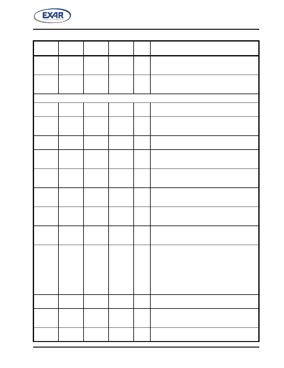
TXRDYB#
-
12
6
O
UART channel B Transmitter Ready (active low). The out-
put provides the TX FIFO/THR status for transmit channel
B. See Table 2. If it is not used, leave it unconnected.
RXRDYB#
-
23
18
O
UART channel B Receiver Ready (active low). This out-
put provides the RX FIFO/RHR status for receive channel
B. See Table 2. If it is not used, leave it unconnected.
MODEM OR SERIAL I/O INTERFACE
TXA
11
13
7
O
UART channel A Transmit Data. If it is not used, leave it
unconnected.
RXA
10
11
5
I
UART channel A Receive Data. Normal receive data
input must idle at logic 1 condition. If it is not used, tie it to
VCC or pull it high via a 100k ohm resistor.
RTSA#
32
36
33
O
UART channel A Request-to-Send (active low) or general
purpose output. If it is not used, leave it unconnected.
CTSA#
36
40
38
I
UART channel A Clear-to-Send (active low) or general
purpose input. This input should be connected to VCC
when not used. This input has no effect on the UART.
DTRA#
33
37
34
O
UART channel A Data-Terminal-Ready (active low) or
general purpose output. If it is not used, leave it uncon-
nected.
DSRA#
37
41
39
I
UART channel A Data-Set-Ready (active low) or general
purpose input. This input should be connected to VCC
when not used. This input has no effect on the UART.
CDA#
38
42
40
I
UART channel A Carrier-Detect (active low) or general
purpose input. This input should be connected to VCC
when not used. This input has no effect on the UART.
RIA#
39
43
41
I
UART channel A Ring-Indicator (active low) or general
purpose input. This input should be connected to VCC
when not used. This input has no effect on the UART.
OP2A#
31
35
32
O
Output Port 2 Channel A - The output state is defined by
the user and through the software setting of MCR[3].
INTA is set to the active mode and OP2A# output to a
logic 0 when MCR[3] is set to a logic 1. INTA is set to the
three state mode and OP2A# to a logic 1 when MCR[3] is
set to a logic 0. See MCR[3]. This output should not be
used as a general output else it will disturb the INTA out-
put functionality. If it is not used at all, leave it uncon-
nected.
TXB
12
14
8
O
UART channel B Transmit Data. If it is not used, leave it
unconnected.
RXB
9
10
4
I
UART channel B Receive Data. Normal receive data
input must idle at logic 1 condition. If it is not used, tie it to
VCC or pull it high via a 100k ohm resistor.
RTSB#
24
27
22
O
UART channel B Request-to-Send (active low) or general
purpose output. If it is not used, leave it unconnected.
Pin Description
NAME
40-PDIP
PIN #
44-PLCC
PIN #
48-TQFP
PIN #
TYPE
DESCRIPTION
相关PDF资料 |
PDF描述 |
|---|---|
| XR16C850CM-F | IC UART FIFO 128B 48TQFP |
| XR16L2750IM-F | IC UART FIFO 64B DUAL 48TQFP |
| ST16C2550CQ48-F | IC DUART FIFO 16B 48TQFP |
| XR88C681CP/40-F | IC UART CMOS DUAL 40PDIP |
| AT89C51RB2-RLRIM | IC MCU FLASH 8051 16K 5V 44-VQFP |
相关代理商/技术参数 |
参数描述 |
|---|---|
| ST16C2550IQ48TR-F | 功能描述:UART 接口集成电路 DUAL UART W/16BYTE FIFO RoHS:否 制造商:Texas Instruments 通道数量:2 数据速率:3 Mbps 电源电压-最大:3.6 V 电源电压-最小:2.7 V 电源电流:20 mA 最大工作温度:+ 85 C 最小工作温度:- 40 C 封装 / 箱体:LQFP-48 封装:Reel |
| ST16C2552 | 制造商:EXAR 制造商全称:EXAR 功能描述:2.97V TO 5.5V DUAL UART WITH 16-BYTE FIFO |
| ST16C2552_06 | 制造商:EXAR 制造商全称:EXAR 功能描述:2.97V TO 5.5V DUAL UART WITH 16-BYTE FIFO |
| ST16C2552CJ | 制造商:EXAR 功能描述:IC , Dual UART 4MBPS 5.5 44 PLCC 制造商:Exar Corporation 功能描述: 制造商:XIC 功能描述: 制造商:Exar Corporation 功能描述:UART, 44 Pin, Plastic, PLCC |
| ST16C2552CJ-0A-EB | 功能描述:界面开发工具 Supports C2550 44 ld PLCC, ISA Interface RoHS:否 制造商:Bourns 产品:Evaluation Boards 类型:RS-485 工具用于评估:ADM3485E 接口类型:RS-485 工作电源电压:3.3 V |
发布紧急采购,3分钟左右您将得到回复。