- 您现在的位置:买卖IC网 > PDF目录98143 > ST52F510G2B6 (STMICROELECTRONICS) 8-BIT, FLASH, 24 MHz, MICROCONTROLLER, PDIP28 PDF资料下载
参数资料
| 型号: | ST52F510G2B6 |
| 厂商: | STMICROELECTRONICS |
| 元件分类: | 微控制器/微处理器 |
| 英文描述: | 8-BIT, FLASH, 24 MHz, MICROCONTROLLER, PDIP28 |
| 封装: | PLASTIC, DIP-28 |
| 文件页数: | 73/106页 |
| 文件大小: | 1340K |
| 代理商: | ST52F510G2B6 |
第1页第2页第3页第4页第5页第6页第7页第8页第9页第10页第11页第12页第13页第14页第15页第16页第17页第18页第19页第20页第21页第22页第23页第24页第25页第26页第27页第28页第29页第30页第31页第32页第33页第34页第35页第36页第37页第38页第39页第40页第41页第42页第43页第44页第45页第46页第47页第48页第49页第50页第51页第52页第53页第54页第55页第56页第57页第58页第59页第60页第61页第62页第63页第64页第65页第66页第67页第68页第69页第70页第71页第72页当前第73页第74页第75页第76页第77页第78页第79页第80页第81页第82页第83页第84页第85页第86页第87页第88页第89页第90页第91页第92页第93页第94页第95页第96页第97页第98页第99页第100页第101页第102页第103页第104页第105页第106页
69/106
11 WATCHDOG TIMER
11.1 Functional Description
The Watchdog Timer (WDT) is used to detect the
occurrence of a software fault, usually generated
by external interference or by unforeseen logical
conditions, which causes the application program
to abandon its normal sequence. The WDT circuit
generates an ICU reset on expiry of a programmed
time period, unless the program refreshes the
WDT before the end of the programmed time
delay. Sixteen different delays can be selected by
using the WDT configuration register.
After the end of the delay programmed by the
configuration register, if the WDT is active, it starts
a reset cycle pulling the reset signal low.
Once the WDT is activated, the application
program has to refresh the counter (by the
WDTRFR instruction) during normal operation in
order to prevent an ICU reset.
In ST52F510/F513/F514 devices it is possible to
choose
between
“Hardware”
or
“Software”
Watchdog.
The
Hardware
WDT
allows
the
counting to avoid unwanted stops for external
interferences. The first mode is always enabled
unless the Option Byte 4 (WDT_EN) is written with
a special code (10101010b): only this code can
switch the WDT in “Software” Mode, the other 255
possibilities keep the “Hardware” Mode enabled.
The WDT is started and refreshed by using the
WDTRFR instruction. When the software mode is
enabled, the WDTSLP instruction stops the WDT
avoiding timeout resets.
When the WDT is in Hardware Mode, neither the
WDTSLP instruction nor external interference can
stop the counting. The “Hardware” WDT is always
enabled after a Reset.
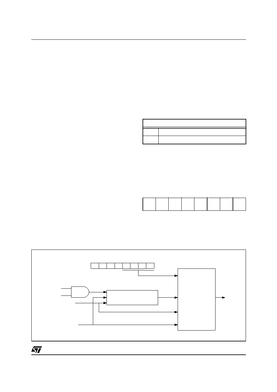
Figure 11.1 Watchdog Block Diagram
The working frequency of WDT (PRES CLK in the
Figure 11.1) is equal to the clock master. The clock
master is divided by 500, obtaining the WDT CLK
signal that is used to fix the timeout of the WDT.
According to the WDT_CR Configuration Register
values, a WDT delay between 0.1ms and 937.5ms
can be defined when the clock master is 5 MHz. By
changing the clock master frequency the timeout
delay
can
be
calculated
according
to
the
configuration register values. The first 4 bits of the
WDT_CR register are used, obtaining 16 different
delays.
11.2 Register Description
SW Watchdog Enable (WDT_EN)
Option Byte 4 (04h)
Reset Value: 0000 0000 (00h)
Bit 7-0: WDTEN7-0 SW Watchdog Enable byte
Writing the code 10101010 in this byte the
Software Watchdog mode is enabled.
D0
D1
D2
D3
Configuration Register
RESET
WDTRFR
PRES CLK = CLK MASTER
WDTSLP
PRESCALER
WDT
RESET
GENERATOR
RESET
W TD CLK
Table 11.1 Watchdog Timing Range (5 MHz)
WDT timeout period (ms)
min
0.1
max
937.5
70
WDTEN7 WDTEN6 WDTEN5 WDTEN4 WDTEN3 WDTEN2 WDTEN1 WDTEN0
相关PDF资料 |
PDF描述 |
|---|---|
| ST52F510G3B6 | 8-BIT, FLASH, 24 MHz, MICROCONTROLLER, PDIP28 |
| ST52F514G3B6 | 8-BIT, FLASH, 24 MHz, MICROCONTROLLER, PDIP28 |
| ST52F513G3B6 | 8-BIT, FLASH, 24 MHz, MICROCONTROLLER, PDIP28 |
| ST52F513Y1B6 | 8-BIT, FLASH, 24 MHz, MICROCONTROLLER, PDIP16 |
| ST52F513Y2B6 | 8-BIT, FLASH, 24 MHz, MICROCONTROLLER, PDIP16 |
相关代理商/技术参数 |
参数描述 |
|---|---|
| ST52F510GMB6 | 制造商:STMICROELECTRONICS 制造商全称:STMicroelectronics 功能描述:8-BIT INTELLIGENT CONTROLLER UNIT ICU Two Timer/PWMs, ADC, I2C, SPI, SCI |
| ST52F510GMM6 | 制造商:STMICROELECTRONICS 制造商全称:STMicroelectronics 功能描述:8-BIT INTELLIGENT CONTROLLER UNIT ICU Two Timer/PWMs, ADC, I2C, SPI, SCI |
| ST52F510YMM6 | 制造商:STMICROELECTRONICS 制造商全称:STMicroelectronics 功能描述:8-BIT INTELLIGENT CONTROLLER UNIT ICU Two Timer/PWMs, ADC, I2C, SPI, SCI |
| ST52F513 | 制造商:STMICROELECTRONICS 制造商全称:STMicroelectronics 功能描述:8-BIT INTELLIGENT CONTROLLER UNIT ICU Two Timer/PWMs, ADC, I2C, SPI, SCI |
| ST52F513FMB6 | 制造商:STMICROELECTRONICS 制造商全称:STMicroelectronics 功能描述:8-BIT INTELLIGENT CONTROLLER UNIT ICU Two Timer/PWMs, ADC, I2C, SPI, SCI |
发布紧急采购,3分钟左右您将得到回复。