- 您现在的位置:买卖IC网 > PDF目录98145 > ST72622K2B1 (STMICROELECTRONICS) 8-BIT, MROM, 8 MHz, MICROCONTROLLER, PQFP44 PDF资料下载
参数资料
| 型号: | ST72622K2B1 |
| 厂商: | STMICROELECTRONICS |
| 元件分类: | 微控制器/微处理器 |
| 英文描述: | 8-BIT, MROM, 8 MHz, MICROCONTROLLER, PQFP44 |
| 封装: | TQFP-44 |
| 文件页数: | 85/136页 |
| 文件大小: | 2475K |
| 代理商: | ST72622K2B1 |
第1页第2页第3页第4页第5页第6页第7页第8页第9页第10页第11页第12页第13页第14页第15页第16页第17页第18页第19页第20页第21页第22页第23页第24页第25页第26页第27页第28页第29页第30页第31页第32页第33页第34页第35页第36页第37页第38页第39页第40页第41页第42页第43页第44页第45页第46页第47页第48页第49页第50页第51页第52页第53页第54页第55页第56页第57页第58页第59页第60页第61页第62页第63页第64页第65页第66页第67页第68页第69页第70页第71页第72页第73页第74页第75页第76页第77页第78页第79页第80页第81页第82页第83页第84页当前第85页第86页第87页第88页第89页第90页第91页第92页第93页第94页第95页第96页第97页第98页第99页第100页第101页第102页第103页第104页第105页第106页第107页第108页第109页第110页第111页第112页第113页第114页第115页第116页第117页第118页第119页第120页第121页第122页第123页第124页第125页第126页第127页第128页第129页第130页第131页第132页第133页第134页第135页第136页
ST7262
52/136
10.3 TIMEBASE UNIT (TBU)
10.3.1 Introduction
The Timebase unit (TBU) can be used to generate
periodic interrupts.
10.3.2 Main Features
■ 8-bit upcounter
■ Programmable prescaler
■ Period between interrupts: max. 8.1ms (at 8
MHz fCPU )
■ Maskable interrupt
■ Cascadable with PWM/ART TImer
10.3.3 Functional Description
The TBU operates as a free-running upcounter.
When the TCEN bit in the TBUCSR register is set
by software, counting starts at the current value of
the TBUCV register. The TBUCV register is incre-
mented at the clock rate output from the prescaler
selected by programming the PR[2:0] bits in the
TBUCSR register.
When the counter rolls over from FFh to 00h, the
OVF bit is set and an interrupt request is generat-
ed if ITE is set.
The user can write a value at any time in the
TBUCV register.
If the cascading option is selected (CAS bit=1 in
the TBUCSR register), the TBU and the the ART
TImer counters act together as a 16-bit counter. In
this case, the TBUCV register is the high order
byte, the ART counter (ARTCAR register) is the
low order byte. Counting is clocked by the ART
timer clock (Refer to the description of the ART
Timer ARTCSR register).
10.3.4 Programming Example
In this example, timer is required to generate an in-
terrupt after a delay of 1 ms.
Assuming that fCPU is 8 MHz and a prescaler divi-
sion factor of 256 will be programmed using the
PR[2:0] bits in the TBUCSR register, 1 ms = 32
TBU timer ticks.
In this case, the initial value to be loaded in the
TBUCV must be (256-32) = 224 (E0h).
ld A, E0h
ld TBUCV, A
; Initialize counter value
ld A 1Fh
;
ld TBUCSR, A
; Prescaler factor = 256,
; interrupt enable,
; TBU enable
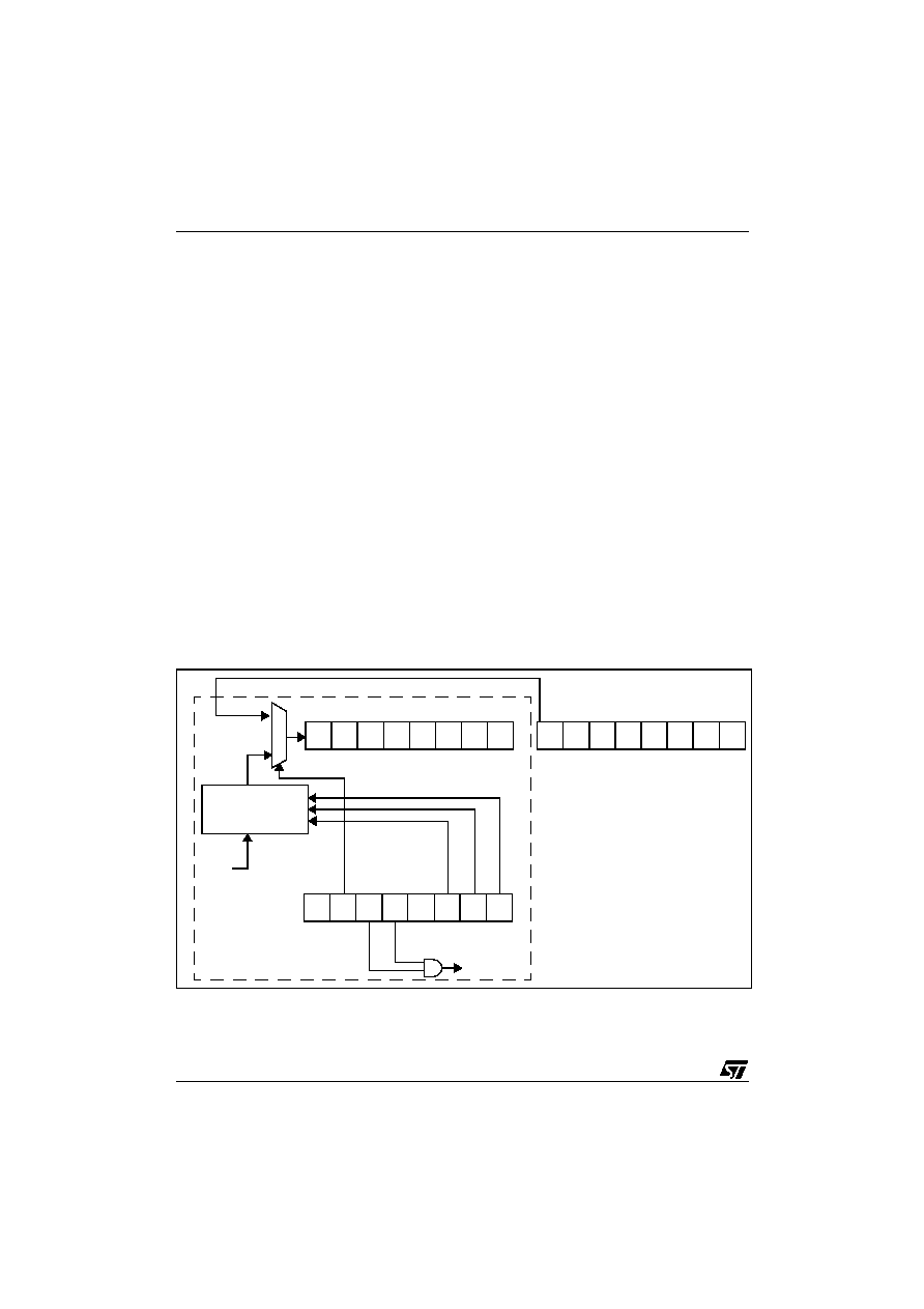
Figure 38. TBU Block Diagram
TBU 8-BIT UPCOUNTER (TBUCV REGISTER)
INTERRUPT REQUEST
TBU PRESCALER
fCPU
TBUCSR REGISTER
PR1 PR0
PR2
TCEN
ITE
OVF
MSB
LSB
ART PWM TIMER 8-BIT COUNTER
MSB
LSB
CAS
0
1
TBU
ART TIMER CARRY BIT
0
相关PDF资料 |
PDF描述 |
|---|---|
| ST72P621J4B1 | 8-BIT, MROM, 8 MHz, MICROCONTROLLER, PDIP32 |
| ST72P621J4T1 | 8-BIT, MROM, 8 MHz, MICROCONTROLLER, PDSO34 |
| ST72621J2B1 | 8-BIT, MROM, 8 MHz, MICROCONTROLLER, PDIP20 |
| ST72621J2T1 | 8-BIT, MROM, 8 MHz, MICROCONTROLLER, PDSO20 |
| ST72P621L4M1 | 8-BIT, MROM, 8 MHz, MICROCONTROLLER, PDSO34 |
相关代理商/技术参数 |
参数描述 |
|---|---|
| ST7263-EMU2 | 功能描述:仿真器/模拟器 ST7 Emulator Board RoHS:否 制造商:Blackhawk 产品:System Trace Emulators 工具用于评估:C6000, C5000, C2000, OMAP, DAVINCI, SITARA, TMS470, TMS570, ARM 7/9, ARM Cortex A8/R4/M3 用于:XDS560v2 |
| ST7265X-EVAL/MS | 制造商:STMicroelectronics 功能描述:ST6 EVAL BD - Bulk |
| ST7265X-EVAL/PFD | 制造商:STMicroelectronics 功能描述:USB FLASH EVAL - Bulk |
| ST7266 | 制造商:6940 功能描述:ST7266 |
| ST7267C8T1L | 制造商:STMicroelectronics 功能描述: |
发布紧急采购,3分钟左右您将得到回复。