- 您现在的位置:买卖IC网 > PDF目录374939 > STIR4200S (Electronic Theatre Controls, Inc.) USB/lrDA Bridge Controller PDF资料下载
参数资料
| 型号: | STIR4200S |
| 厂商: | Electronic Theatre Controls, Inc. |
| 英文描述: | USB/lrDA Bridge Controller |
| 中文描述: | 的USB / lrDA桥控制器 |
| 文件页数: | 9/21页 |
| 文件大小: | 308K |
| 代理商: | STIR4200S |
3-4200-D1-2.0-0403
9
STIr4200
USB/IrDA Bridge Controller
O F F I C I A L P R O D U C T D O C U M E N T A T I O N
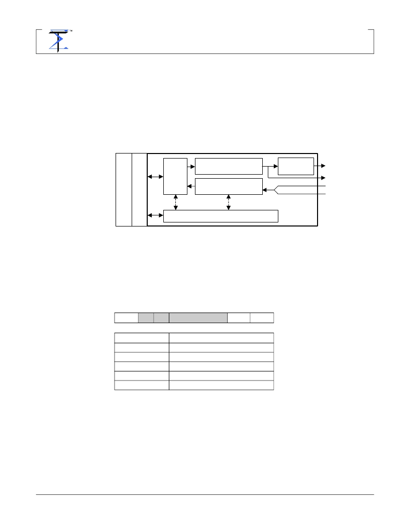
4.4.
Digital IR Transceiver
The Digital IR Transceiver is responsible for driving the transmit diode and receiving
the digital input from an analog IR front end. The primary components are the trans-
mit modulator, the receive demodulator, the FIFO, the analog transmit section, and
the register array. Figure 3 shows a block diagram of the Digital IR Transceiver. By
programming the registers in the register array, the device
’
s operation is deter-
mined. Various registers are used to specify operations such as the modulation
scheme, the baud rate, the current frame size in the FIFO, the RX input selection,
etc. The FIFO is 4K bytes in size.
In steady state transmit operation, the USB controller is filling the FIFO with data
while the Digital IR Transceiver is emptying it via the transmit modulator. In steady
state receive operation, the USB controller is emptying the FIFO while the RX
demodulator is filling the FIFO.
4.5.
FIFO Contents
Data sent to the USB controller for transmission by the TX modulator must be orga-
nized into frames. An IrLAP frame is made up of the following portions:
The NDIS IR stack only provides the A, C, and I fields to the NDIS mini-port device
driver that communicates with the USB/IrDA transceiver. Hence, the mini-port must
fill in the BOF, FCS, and EOF fields. Additionally, the driver must add a 2-byte
header ID code and a 2-byte frame size to the packet before passing the packet
onto the USB stack for delivery to the USB/IrDA transceiver. There are additional
special characters and required escape sequences depending upon the rate of
transfer. Details on the frame format for each of the support rates is discussed in the
following sections.
BOF
A
C
I
FCS
EOF
BOF
Beginning of frame(s)
A
C
I
Address field
Control field
Information field
Frame check sequence (CRC)
End of frame
Table 9. IrLAP Frame
FCS
EOF
TX Modulator
(ASK, IrDA FIR,MIR,SIR)
RX Demodulator
(ASK, IrDA FIR,MIR,SIR)
FIFO
Register Array
Analog TX
Section
RX
SLOW
RX
FAST
U
U
TX
DIODE
TX
DATA
Figure 3. Block Diagram of Digital IR Transceiver
相关PDF资料 |
PDF描述 |
|---|---|
| STLR4200 | USB/lrDA Bridge Controller |
| STLR4200S | USB/lrDA Bridge Controller |
| STIR4210 | USB 2.0 Hi-Speed to irDA Bridge |
| STIR4210N | USB 2.0 Hi-Speed to irDA Bridge |
| STIR4220 | USB 2.0 Hi-Speed to irDA Bridge |
相关代理商/技术参数 |
参数描述 |
|---|---|
| STIR4210 | 制造商:未知厂家 制造商全称:未知厂家 功能描述:USB 2.0 Hi-Speed to irDA Bridge |
| STIR4210N | 制造商:未知厂家 制造商全称:未知厂家 功能描述:USB 2.0 Hi-Speed to irDA Bridge |
| STIR4220 | 制造商:未知厂家 制造商全称:未知厂家 功能描述:USB 2.0 Hi-Speed to irDA Bridge |
| STIR4220N | 制造商:未知厂家 制造商全称:未知厂家 功能描述:USB 2.0 Hi-Speed to irDA Bridge |
| STI-SD/128 | 功能描述:存储卡 128MB 2.7 to 3.6V Operation RoHS:否 制造商:Olimex Ltd. 产品:SD 存储容量: 连续读取: 连续写入: 有源模式电流: 工作电源电压: 最大工作温度: 尺寸: |
发布紧急采购,3分钟左右您将得到回复。