- 您现在的位置:买卖IC网 > PDF目录98148 > STK17T88-RF45 PROGRAMMABLE TIMER, PDSO48 PDF资料下载
参数资料
| 型号: | STK17T88-RF45 |
| 元件分类: | 时钟/数据恢复及定时提取 |
| 英文描述: | PROGRAMMABLE TIMER, PDSO48 |
| 封装: | 0.300 INCH, ROHS COMPLIANT, PLASTIC, SSOP-48 |
| 文件页数: | 10/29页 |
| 文件大小: | 535K |
| 代理商: | STK17T88-RF45 |
第1页第2页第3页第4页第5页第6页第7页第8页第9页当前第10页第11页第12页第13页第14页第15页第16页第17页第18页第19页第20页第21页第22页第23页第24页第25页第26页第27页第28页第29页
18
STK17T88
Jan, 2008
Document Control #ML0024 Rev 2.0
To set or clear the Alarm registers, set the write bit
“W” (in the Flags register at 0x7FF0) to a “1” to
enable writes to the Alarm registers. Write an alarm-
value to the alarm registers and then reset the write
bit to “0” to disable writes.
WATCHDOG TIMER
The watchdog timer is designed to interrupt or reset
the processor should its program get hung in a loop
and not respond in a timely manner. The software
must reload the watchdog timer before it counts
down to zero to prevent this interrupt or reset.
The watchdog timer is a free-running-down counter
that uses the 32Hz clock (31.25 ms) derived from
the crystal oscillator. The watchdog timer function
does not operate unless the oscillator is running.
The watchdog counter is loaded with a starting value
from the load register and then counts down to zero,
setting the watchdog flag (WDF) and generating an
interrupt if the watchdog interrupt is enabled. The
watchdog flag bit is reset when the Flags register is
read. The operating software would normally reload
the counter by setting the watchdog strobe bit
(WDS) to 1 within the timing interval programmed
into the load register.
To use the watchdog timer to reset the processor on
timeout, the INT is tied to processor master reset
and Interrupt register is programmed to 24h to
enable interrupts to pulse the reset pin on timeout.
To load the watchdog timer, set a new value into the
load register by writing a “0” to the watchdog write bit
(WDW) of the watchdog register (at 0x7FF7). Then
load a new value into the load register. Once the
new value is loaded, the watchdog write bit is then
set to 1 to disable watchdog writes. The watchdog
strobe bit (WDS) is set to 1 to load this value into the
watchdog timer. Note: Setting the load register to
zero will disable the watchdog timer function.
The system software should initialize the watchdog
load register on power-up to the desired value since
the register is not non-volatile.
POWER MONITOR
The STK17T88 provides a power monitor function.
The power monitor is based on an internal band-gap
reference circuit that compares the VCC voltage to
VSWITCH.
When the power supply drops below VSWITCH, the
real time clock circuit is switched to the backup sup-
ply (battery or capacitor).
When operating from the backup source, no data
may be read or written and the clock functions are
not available to the user. The clock continues to
operate in the background. Updated clock data is
available to the user tHRECALL delay after VCC has
been restored to the device.
When the power is lost, the PF flag in the Flags reg-
ister is set to indicate the power failure and an inter-
rupt is generated if the power fail interrupt is enabled
(interrupt register=20h). The INT line would normally
be tied to the processor master reset input to per-
form power-off reset.
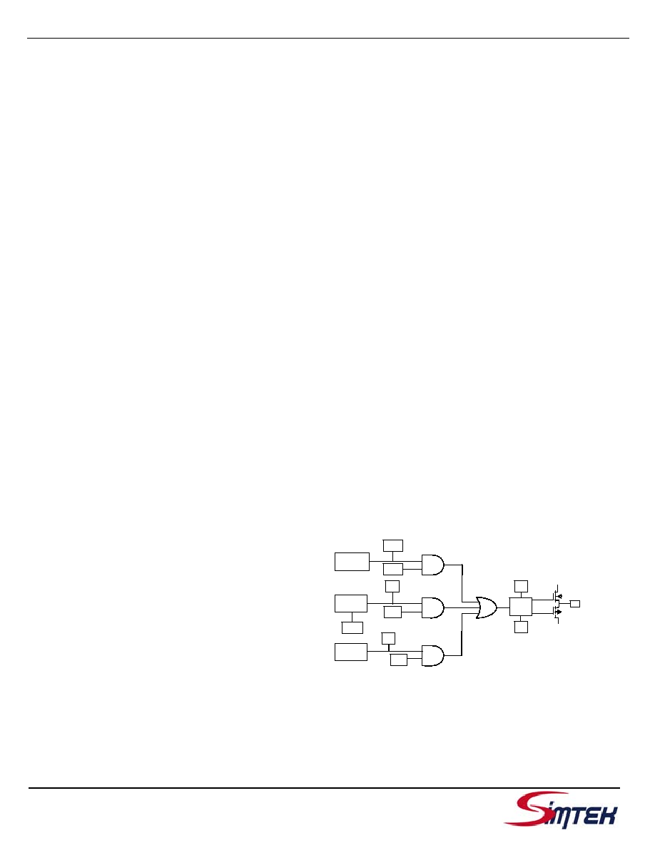
INTERRUPTS
The STK17T88 has a Flags register, Interrupt regis-
ter, and interrupt logic that can interrupt the micro-
controller or general a power-up master reset signal.
There are three potential interrupt sources: the
watchdog timer, the power monitor, and the clock
alarm. Each can be individually enabled to drive the
INT pin by setting the appropriate bit in the Interrupt
register. In addition, each has an associated flag bit
in the Flags register that the host processor can
read to determine the interrupt source. Two bits in
the interrupt register determine the operation of the
INT pin driver.
A functional diagram of the interrupt logic is shown
below.
Figure 6. Interrupt Block Diagram
Watchdog
Timer
Power
Monitor
Clock
Alarm
PF
PFE
VINT
AIE
AF
P/L
H/L
Pin
Driver
INT
VCC
WIE
WDF
VSS
相关PDF资料 |
PDF描述 |
|---|---|
| STK17T88-RF25ITR | PROGRAMMABLE TIMER, PDSO48 |
| STK17TA8-R25I | REAL TIME CLOCK, PDSO48 |
| STK17TA8-R35 | REAL TIME CLOCK, PDSO48 |
| STK17TA8-W25 | REAL TIME CLOCK, PDIP40 |
| STK17TA8-R45 | REAL TIME CLOCK, PDSO48 |
相关代理商/技术参数 |
参数描述 |
|---|---|
| STK17T88-RF45I | 功能描述:NVRAM 32Kbx8+RTC 2.7-3.6V RoHS:否 制造商:Maxim Integrated 数据总线宽度:8 bit 存储容量:1024 Kbit 组织:128 K x 8 接口类型:Parallel 访问时间:70 ns 电源电压-最大:5.5 V 电源电压-最小:4.5 V 工作电流:85 mA 最大工作温度:+ 70 C 最小工作温度:0 C 封装 / 箱体:EDIP 封装:Tube |
| STK17T88-RF45ITR | 功能描述:NVRAM 32Kbx8+RTC 2.7-3.6V RoHS:否 制造商:Maxim Integrated 数据总线宽度:8 bit 存储容量:1024 Kbit 组织:128 K x 8 接口类型:Parallel 访问时间:70 ns 电源电压-最大:5.5 V 电源电压-最小:4.5 V 工作电流:85 mA 最大工作温度:+ 70 C 最小工作温度:0 C 封装 / 箱体:EDIP 封装:Tube |
| STK17T88-RF45TR | 功能描述:NVRAM 32Kbx8+RTC 2.7-3.6V RoHS:否 制造商:Maxim Integrated 数据总线宽度:8 bit 存储容量:1024 Kbit 组织:128 K x 8 接口类型:Parallel 访问时间:70 ns 电源电压-最大:5.5 V 电源电压-最小:4.5 V 工作电流:85 mA 最大工作温度:+ 70 C 最小工作温度:0 C 封装 / 箱体:EDIP 封装:Tube |
| STK17TA8-RF25 | 功能描述:NVRAM 128Kbx8+RTC 2.7-3.6V RoHS:否 制造商:Maxim Integrated 数据总线宽度:8 bit 存储容量:1024 Kbit 组织:128 K x 8 接口类型:Parallel 访问时间:70 ns 电源电压-最大:5.5 V 电源电压-最小:4.5 V 工作电流:85 mA 最大工作温度:+ 70 C 最小工作温度:0 C 封装 / 箱体:EDIP 封装:Tube |
| STK17TA8-RF25I | 功能描述:NVRAM 128Kbx8+RTC 2.7-3.6V RoHS:否 制造商:Maxim Integrated 数据总线宽度:8 bit 存储容量:1024 Kbit 组织:128 K x 8 接口类型:Parallel 访问时间:70 ns 电源电压-最大:5.5 V 电源电压-最小:4.5 V 工作电流:85 mA 最大工作温度:+ 70 C 最小工作温度:0 C 封装 / 箱体:EDIP 封装:Tube |
发布紧急采购,3分钟左右您将得到回复。