参数资料
| 型号: | SX1509BULTRT |
| 厂商: | Semtech |
| 文件页数: | 10/41页 |
| 文件大小: | 0K |
| 描述: | IC GPIO EXPANDER I2C 16CH 28QFN |
| 特色产品: | SX1508/SX1509 GPIO Expanders |
| 标准包装: | 1 |
| 接口: | I²C |
| 输入/输出数: | 16 |
| 中断输出: | 是 |
| 频率 - 时钟: | 400kHz |
| 电源电压: | 1.2 V ~ 3.6 V |
| 工作温度: | -40°C ~ 85°C |
| 安装类型: | 表面贴装 |
| 封装/外壳: | 28-UFQFN 裸露焊盘 |
| 供应商设备封装: | 28-QFN-UT(4x4) |
| 包装: | 标准包装 |
| 包括: | LED 驱动器 / 小键盘引擎 |
| 其它名称: | SX1509IULDKR SX1509IULDKR-ND |
第1页第2页第3页第4页第5页第6页第7页第8页第9页当前第10页第11页第12页第13页第14页第15页第16页第17页第18页第19页第20页第21页第22页第23页第24页第25页第26页第27页第28页第29页第30页第31页第32页第33页第34页第35页第36页第37页第38页第39页第40页第41页
ADVANCED COMMUNICATIONS & SENSING
Rev 1 – 30
th Oct. 2009
18
www.semtech.com
SX1507/SX1508/SX1509
World’s Lowest Voltage Level Shifting GPIO
with LED Driver and Keypad Engine
4.6.4
Polarity Inverter
Each IO’s polarity can be individually inverted by setting corresponding bit in RegPolarity register. Please note
that polarity inversion can also be combined with level shifting feature.
4.7
Interrupt (NINT)
At start-up, the transition detection logic is reset, and NINT is released to a high-impedance state. The interrupt
mask register is set to 0xFF, disabling the interrupt output for transitions on all I/O ports. The transition flags are
cleared to indicate no data changes.
An interrupt NINT can be generated on any programmed combination of I/Os rising and/or falling edges through
the RegInterruptMask and RegSense registers.
If needed, the I/Os which triggered the interrupt can then be identified by reading RegInterruptSource register.
When NINT is low (i.e. interrupt occurred), it can be reset back high (i.e. cleared) by writing 0xFF in
RegInterruptSource (this will also clear corresponding bits in RegEventStatus register).
The interrupt can also be cleared automatically when reading RegData register (Cf. RegMisc)
Example: We want to detect rising edge of I/O[1] on SX1508 (NINT will go low).
1.
We enable interrupt on I/O[1] in RegInterruptMask
RegInterruptMask =“XXXXXX0X”
2.
We set edge sense for I/O[1] in RegSense
RegSenseLow =“XXXX01XX”
Please note that independently from the “user defined” process described above the keypad engine, when
enabled, also uses NINT to indicate a key press.
Hence we have NINT = “user defined condition occurred” OR “keypad engine condition occurred”.
4.8
Clock Management
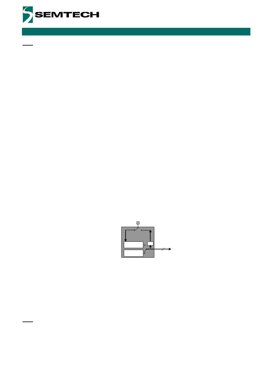
A main oscillator clock fOSC is needed by the LED driver, keypad engine and debounce features.
Clock management block is illustrated in figure below.
OSCIO
Clock
Mgmt
Internal
Oscillator
External
Clock
fOSC
Div
Figure 14 – Clock Management Overview
The block is configured in register RegClock (Cf §5 for more detailed information):
Selection of internal clock source: none (OFF) or internal oscillator or external clock input from OSCIN.
Definition of OSCIO pin function (OSCIN or OSCOUT)
OSCOUT frequency setting (sub-multiple of fOSC)
Please note that if needed the OSCOUT feature can be used as an additional GPO (Cf. RegClock)
4.9
LED Driver
4.9.1
Overview
Every IO has its own independent LED driver to perform intensity control, blinking and fading operation. (Cf §6.2
for typical LED connection)
Please note that while all I/Os can perform intensity control (PWM) only some of them additionally include
blinking and breathing features (Cf pin description §1)
The LED drivers of all I/Os share the same clock ClkX configurable in RegMisc[6:4]. Please note that for power
consumption reasons ClkX is OFF by default.
相关PDF资料 |
PDF描述 |
|---|---|
| SX8722I070TRLF | IC ZOOMING ADC 10BIT 16CH 44MLPQ |
| SX8723CWLTDT | IC DAS ADC 16BIT I2C/SRL |
| SX8723E083TDT | IC DAS PRESS/TEMP SENS 12MLPD |
| SX8724CWLTDT | IC DAS ADC 16BIT I2C/SRL |
| SX8724E082TDT | IC DAS PRESS/TEMP SENS 16MLPQ |
相关代理商/技术参数 |
参数描述 |
|---|---|
| SX1509EVK | 制造商:SEMTECH 制造商全称:Semtech Corporation 功能描述:Worlds Lowest Voltage Level |
| SX1509IULTRT | 制造商:SEMTECH 制造商全称:Semtech Corporation 功能描述:Worlds Lowest Voltage Level |
| SX1509QB | 制造商:SEMTECH 制造商全称:Semtech Corporation 功能描述:World’s Lowest Voltage Level Shifting GPIO with LED Driver and Keypad Engine |
| SX1509QBIULTRT | 制造商:Semtech Corporation 功能描述:Voltage Level Shifting GPIO with LED Driver 28-Pin QFN-UT EP T/R 制造商:Semtech Corporation 功能描述:IC ESD/EMI PROT DIODE 制造商:Semtech Corporation 功能描述:16 CHAN LOW VOLT GPIO + PWM |
| SX150A | 功能描述:板上安装压力/力传感器 0 to 150psia BUTTON UNAMP ABSOLUTE 12V RoHS:否 制造商:Honeywell 工作压力:0 bar to 4 bar 压力类型:Gage 准确性:+ / - 0.25 % 输出类型:Digital 安装风格:Through Hole 工作电源电压:5 V 封装 / 箱体:SIP 端口类型:Dual Radial Barbed, Same sides |
发布紧急采购,3分钟左右您将得到回复。