参数资料
| 型号: | SY100E111LEJI TR |
| 厂商: | Micrel Inc |
| 文件页数: | 5/7页 |
| 文件大小: | 0K |
| 描述: | IC CLK FANOUT BUFFER 1:9 28-PLCC |
| 标准包装: | 750 |
| 系列: | 100E, Precision Edge® |
| 类型: | 扇出缓冲器(分配) |
| 电路数: | 1 |
| 比率 - 输入:输出: | 1:9 |
| 差分 - 输入:输出: | 是/是 |
| 输入: | PECL |
| 输出: | PECL |
| 电源电压: | 3 V ~ 5.5 V |
| 工作温度: | -40°C ~ 85°C |
| 安装类型: | 表面贴装 |
| 封装/外壳: | 28-LCC(J 形引线) |
| 供应商设备封装: | 28-PLCC |
| 包装: | 带卷 (TR) |
| 其它名称: | SY100E111LEJITR SY100E111LEJITR-ND |
5
Precision Edge
SY10E111AE/LE
SY100E111AE/LE
Micrel, Inc.
M9999-030509
hbwhelp@micrel.com or (408) 955-1690
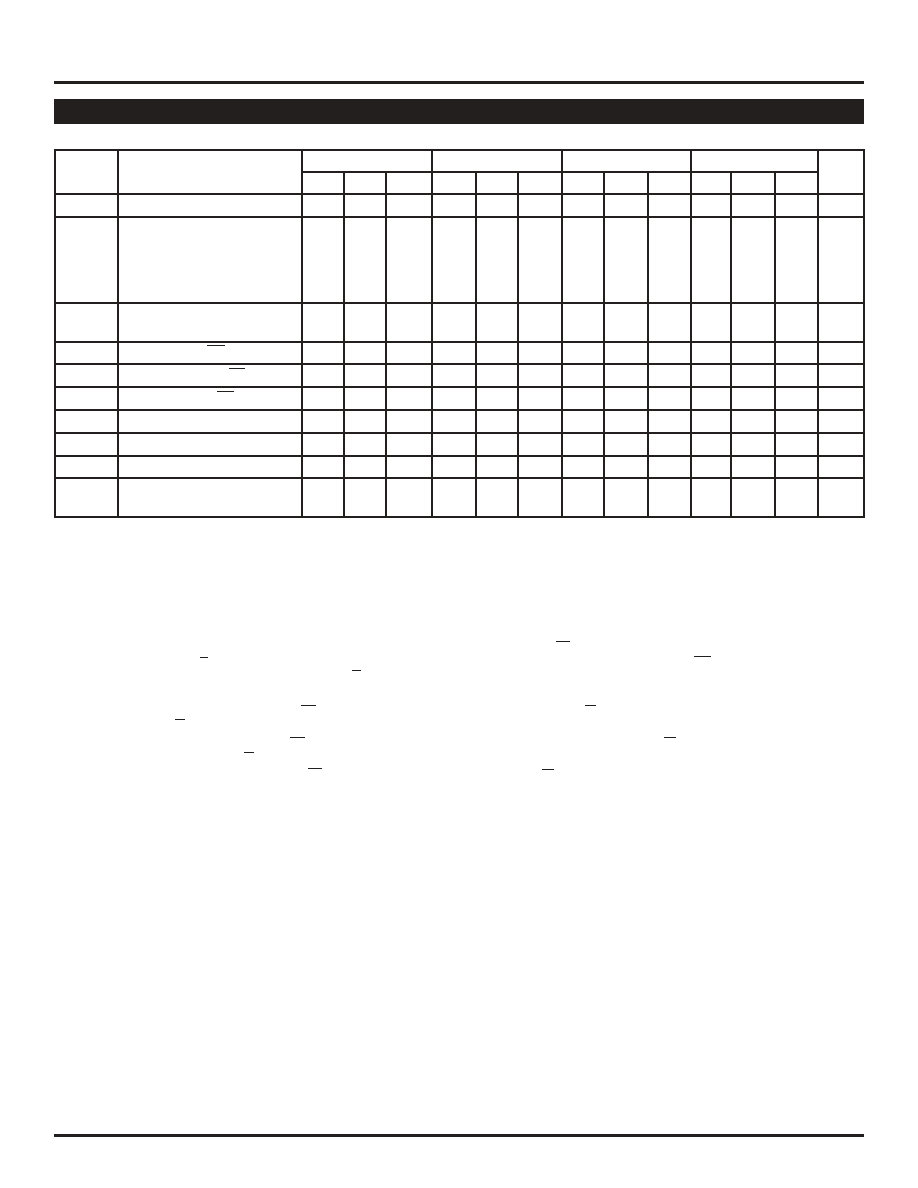
VEE = VEE (Min.) to VEE (Max.); VCC = GND
TA = –40
°CTA = 0°CTA = +25°CTA = +85°C
Symbol
Parameter
Min.
Typ.
Max.
Min.
Typ. Max.
Min.
Typ.
Max. Min.
Typ.
Max.
Unit
fMAX
Maximum Toggle Frequency
800
MHz
tPD
Propagation Delay to Output
ps
IN (differential)(2)
380
—
680
430
—
630
430
—
630
430
—
630
IN (single-ended)(3)
280
—
780
330
—
730
330
—
730
330
—
730
Enable(4)
400
—
900
450
—
850
450
—
850
450
—
850
Disable(4)
400
—
900
450
—
850
450
—
850
450
—
850
tskew
Within-Device Skew(5)
——
75
—
50
—
50
—
50
ps
Part-to-Part Skew (Diff.)
—
250
—
200
—
200
—
200
tS
Set-up Time, EN to IN(6)
250
—
0
200
0
—
200
0
—
200
0
—
ps
tH
Hold Time, IN to EN(7)
0—
–200
0
–200
—
0
–200
—
0
–200
—
ps
tR
Release Time, EN to IN(8)
350
—
100
300
100
—
300
100
—
300
100
—
ps
tJITTER
Random Clock Jitter
1
2
1
2
1
2
1
2
psRMS
VPP
Minimum Input Swing(9)
250
—
250
—
250
—
250
—
mV
VCMR
Common Mode Range(10)
–1.5
—
–0.4
–1.5
—
–0.4
–1.5
—
–0.4
–1.5
—
–0.4
V
tr
Rise/Fall Times
200
—
650
200
—
600
200
—
600
200
—
600
ps
tf
20% to 80%
AC ELECTRICAL CHARACTERISTICS(1)
Notes:
1. Parametric values specified at:
5 volt Power Supply Range
100E111AE Series:
-4.2V to -5.5V.
10E111AE Series
-4.75V to -5.5V.
3 volt Power Supply Range
10/100E111LE Series: -3.0V to -3.8V.
2. The differential propagation delay is defined as the delay from the crossing points of the differential input signals to the crossing point of the
differential output signals.
3. The single-ended propagation delay is defined as the delay from the 50% point of the input signal to the 50% point of the output signal.
4. Enable is defined as the propagation delay from the 50% point of a negative transition on EN to the 50% point of a positive transition on Q (or a
negative transition on Q). Disable is defined as the propagation delay from the 50% point of a positive transition on EN to the 50% point of a
negative transition on Q (or a positive transition on Q).
5. The within-device skew is defined as the worst case difference between any two similar delay paths within a single device.
6. The set-up time is the minimum time that EN must be asserted prior to the next transition of IN/IN to prevent an output response greater than
±75mV to that IN/IN transition (see Figure 1).
7. The hold time is the minimum time that EN must remain asserted after a negative going IN or a positive going IN to prevent an output response
greater than ±75mV to that IN/IN transition (see Figure 2).
8. The release time is the minimum time that EN must be de-asserted prior to the next IN/IN transition to ensure an output response that meets the
specified IN to Q propagation delay and output transition times (see Figure 3).
9. VPP (min) is defined as the minimum input differential voltage which will cause no increase in the propagation delay. The VPP (min) is AC limited
for the E111AE/LE, as a differential input as low as 50mV will still produce full ECL levels at the output.
10. VCMR is defined as the range within the VIH level may vary, with the device still meeting the propagation delay specification. the VIL level must be
such that the peak-to-peak voltage is less than 1.0V and greater than or equal to VPP (min).
For PECL operation: VCMR (max) = VCC – |VCMR (max)| and
VCMR (min) = VCC – |VCMR (min)|
相关PDF资料 |
PDF描述 |
|---|---|
| SY100E111LEJI | IC CLK FANOUT BUFFER 1:9 28-PLCC |
| SY89823LHG | IC CLK BUF MUX TRNSL 2:22 64TQFP |
| SY89874UMI | IC CLOCK BUFF DIVIDER 1:2 16-MLF |
| VI-JWD-MX-B1 | CONVERTER MOD DC/DC 85V 75W |
| VE-J5L-MY | CONVERTER MOD DC/DC 28V 50W |
相关代理商/技术参数 |
参数描述 |
|---|---|
| SY100E111LEJY | 功能描述:缓冲器和线路驱动器 3.3V 1:9 Differential Clock Driver (with Enable) (I Temp, Lead Free) RoHS:否 制造商:Micrel 输入线路数量:1 输出线路数量:2 极性:Non-Inverting 电源电压-最大:+/- 5.5 V 电源电压-最小:+/- 2.37 V 最大工作温度:+ 85 C 安装风格:SMD/SMT 封装 / 箱体:MSOP-8 封装:Reel |
| SY100E111LEJY TR | 功能描述:缓冲器和线路驱动器 3.3V 1:9 Differential Clock Driver (with Enable) (I Temp, Lead Free) RoHS:否 制造商:Micrel 输入线路数量:1 输出线路数量:2 极性:Non-Inverting 电源电压-最大:+/- 5.5 V 电源电压-最小:+/- 2.37 V 最大工作温度:+ 85 C 安装风格:SMD/SMT 封装 / 箱体:MSOP-8 封装:Reel |
| SY100E111LEJYTR | 制造商:MICREL 制造商全称:Micrel Semiconductor 功能描述:5V/3.3V 1:9 DIFFERENTIAL CLOCK DRIVER (w/ENABLE) |
| SY100E111LEJZ | 制造商:MICREL 制造商全称:Micrel Semiconductor 功能描述:5V/3.3V 1:9 DIFFERENTIAL CLOCK DRIVER |
| SY100E111LEJZTR | 制造商:MICREL 制造商全称:Micrel Semiconductor 功能描述:5V/3.3V 1:9 DIFFERENTIAL CLOCK DRIVER |
发布紧急采购,3分钟左右您将得到回复。