参数资料
| 型号: | SY88149HALMG |
| 厂商: | Micrel Inc |
| 文件页数: | 6/10页 |
| 文件大小: | 0K |
| 描述: | IC AMP LIMITING 1.25GBPS 16QFN |
| 标准包装: | 100 |
| 类型: | 限幅后置放大器 |
| 应用: | 光纤学网络 |
| 安装类型: | 表面贴装 |
| 封装/外壳: | 16-VFQFN 裸露焊盘 |
| 供应商设备封装: | 16-QFN(3x3) |
| 包装: | 管件 |
| 其它名称: | 576-3952 |
Micrel, Inc.
SY88149HAL
July 2011
5
M9999-072511-A
hbwhelp@micrel.com or (408) 955-1690
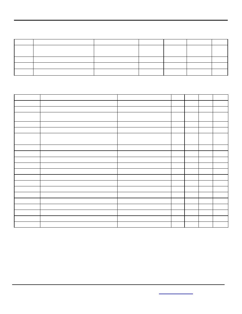
LVTTL DC Electrical Characteristics (Continued)
VCC = 3.0 to 3.6V; TA = –40°C to +85°C, typical values at VCC = 3.3V, TA = 25°C.
Symbol
Parameter
Condition
Min.
Typ.
Max.
Units
IIH_RESET
RESET Input HIGH Current
VIN = VCC
VIN = 2.7V
300
250
A
IIL_RESET
RESET Input LOW Current
VIN = 0.5V
0
mA
VOH
SD/LOS Output HIGH Level
IOH = 100uA
2.1
2.7
V
VOL
SD/LOS Output LOW Level
IOL = 100uA
0.35
0.5
V
AC Electrical Characteristics
VCC = 3.0V to 3.6V; RLOAD = 50 to VCC – 2V; TA = –40°C to +85°C.
Symbol
Parameter
Condition
Min.
Typ.
Max.
Units
tr, tf
Output Rise/Fall Time (20% to 80%)
Note 5
260
ps
tJAM
JAM Enable/Disable Time
2
ns
tAUTORESET
SD Deassert or LOS Assert with Auto Reset
Enabled.
100
120
150
ns
tRESET
RESET time constant
Note 6
5
ns
tON
SD Assert Time/LOS Deassert time
5
ns
tJITTER
Deterministic
Random
Note 7
Note 8
15
5
psPP
psRMS
VID
Differential Input Voltage Swing
Figure 1
5
1800
mVPP
VOD
Differential Output Voltage Swing
VID ≥18mVPP
1500
mVPP
SDAL /LOSDL
Low SD Assert/LOS De- Assert Level
RLOS/SDLVL = 10k, Note 9, 10
4
mVPP
SDDL//LOSAL
Low SD Deassert /LOS Assert Level
RLOS/SDLVL = 10k, Note 10
3
mVPP
HYSL
Low SD/LOS Hysteresis
RLOS/SDLVL = 10k, Note 11
2.5
dB
SDAM/LOSDM
Medium SD Assert/LOS Deassert Level
RLOS/SDLVL = 5k, Note 10
4.76
mVPP
SDDM/LOSAM
Medium SD Deassert /LOS Assert Level
RLOS/SDLVL = 5k, Note 10
3.6
mVPP
HYSM
Medium SD/LOS Hysteresis
RLOS/SDLVL = 5k, Note 11
2
3
4
dB
SDAH/LOSDH
High SD Assert/LOS De- Assert Level
RLOS/SDLVL = 50, Note 10
18
mVPP
SDDH/LOSAH
High SD Deassert/ LOS Assert Level
RLOS/SDLVL = 50, Note 10
12.5
mVPP
HYSH
High SD/LOS Hysteresis
RLOS/SDLVL = 50, Note 11
2
3
4
dB
B-3dB
3dB Bandwidth
750
MHz
AV(Diff)
Differential Voltage Gain
48
dB
S21
Single-Ended Small-Signal Gain
42
dB
Notes:
5.
Amplifier in limiting mode. Input is a 200MHz square wave.
6.
The time between applying RESET and outputs being disabled.
7.
Deterministic jitter measured using 1.25Gbps K28.7 pattern, VID = 10mVPP.
8.
Random jitter measured using 1.25Gbps K28.7 pattern, VID = 10mVPP.
9.
SD is the opposite polarity of LOS. Therefore, an SD Assert parameter is equivalent to a LOS deassert parameter and vice versa.
10. See “Typical Operating Characteristics” for a graph showing how to choose a particular RLOS/SDLVL for a particular assert and
its associated deassert amplitude.
11. This specification defines electrical hysteresis as 20log(SD assert/SD deassert). The ratio between optical hysteresis and electrical hysteresis is
found to vary between 1.5 and 2 depending upon the level of received optical power and ROSA characteristics. Based upon that ratio, the optical
hysteresis corresponding to the electrical hysteresis range 3dB
6dB, shown in the AC Characteristics table, will be 1.5dB-4dB optical hysteresis.
相关PDF资料 |
PDF描述 |
|---|---|
| VE-27H-MW-B1 | CONVERTER MOD DC/DC 52V 100W |
| VI-B32-MX-S | CONVERTER MOD DC/DC 15V 75W |
| MAX3747AEUB+ | IC AMP LIMITING SFP 10-UMAX |
| 74LVC1G00SE-7 | IC GATE NAND SNGL 2INPUT SOT353 |
| LTC1591IN | IC D/A CONV 14BIT PAR 28-DIP |
相关代理商/技术参数 |
参数描述 |
|---|---|
| SY88149HALMG TR | 功能描述:限幅放大器 1.25Gbps GPON Burst Mode Limiting Amplifier RoHS:否 制造商:Micrel 输入电压范围(最大值):3.6 V 工作电源电压:3.3 V 电源电流:40 mA 工作温度范围:- 40 C to + 85 C 封装 / 箱体:MSOP-10 封装:Tube |
| SY88149HALMG-TR | 功能描述:Limiting Postamplifier IC Optical Networks 16-QFN (3x3) 制造商:microchip technology 系列:- 包装:剪切带(CT) 零件状态:停产 类型:限幅后置放大器 应用:光纤学网络 安装类型:表面贴装 封装/外壳:16-VFQFN 裸露焊盘 供应商器件封装:16-QFN(3x3) 标准包装:1 |
| SY88149HL | 制造商:MICREL 制造商全称:Micrel Semiconductor 功能描述:3.3V 1.25Gbps Burst-Mode Limiting |
| SY88149HL_10 | 制造商:MICREL 制造商全称:Micrel Semiconductor 功能描述:3.3V 1.25Gbps Burst-Mode Limiting |
| SY88149HLMG | 功能描述:限幅放大器 Burst-mode post amp with ultra-fast SD assert time for GEPON/GPON OLT (ROHS Compliant) RoHS:否 制造商:Micrel 输入电压范围(最大值):3.6 V 工作电源电压:3.3 V 电源电流:40 mA 工作温度范围:- 40 C to + 85 C 封装 / 箱体:MSOP-10 封装:Tube |
发布紧急采购,3分钟左右您将得到回复。