- 您现在的位置:买卖IC网 > PDF目录20046 > SY88982LMG TR (Micrel Inc)IC LASER DRVR 2.7GBPS 3.6V 16MLF PDF资料下载
参数资料
| 型号: | SY88982LMG TR |
| 厂商: | Micrel Inc |
| 文件页数: | 8/10页 |
| 文件大小: | 0K |
| 描述: | IC LASER DRVR 2.7GBPS 3.6V 16MLF |
| 标准包装: | 1,000 |
| 类型: | 激光二极管驱动器(光纤) |
| 数据速率: | 2.7Gbps |
| 通道数: | 1 |
| 电源电压: | 3 V ~ 3.6 V |
| 电流 - 电源: | 48mA |
| 电流 - 调制: | 90mA |
| 工作温度: | -40°C ~ 85°C |
| 封装/外壳: | 16-VFQFN 裸露焊盘,16-MLF? |
| 供应商设备封装: | 16-MLF?(3x3) |
| 包装: | 带卷 (TR) |
| 安装类型: | 表面贴装 |
| 其它名称: | SY88982LMGTR SY88982LMGTR-ND |
�� ��������
��������Micrel,� Inc.�
�Application� Information�
�The� typical� applications� diagram� on� the� first� page�
�shows� how� to� connect� the� driver� to� the� laser,� single�
�ended.� To� improve� transition� time� and� laser�
�response,� the� laser� can� be� driven� differentially� as�
�shown� in� Figures� 3� and� 4.� Driving� the� laser�
�differentially� will� also� minimize� the� crosstalk� with� the�
�rest� of� the� circuitry� on� the� board,� especially� the�
�receiver.�
�DC-Coupling�
�In� addition� to� the� low� power� consumption� and� high�
�modulation� current,� the� SY88982L� offers� a� high�
�compliance� voltage.� As� can� be� seen� in� the� “Typical�
�Operating� Characteristics”� section� (I� MOD� vs.� V� MOD�
�curves),� the� minimum� voltage� needed� at� the� output�
�of� the� driver� for� proper� operation� is� less� than� 600mV,�
�leaving� a� large� headroom,� V� CC� -600mV,� to� the� laser�
�with� the� damping� resistor.� To� show� the� importance�
�of� this� high� compliance� voltage,� consider� the� voltage�
�drops� along� the� path� from� V� CC� to� ground� through� the�
�laser,� damping� resistor,� and� driver:�
�V� CC� =� Driver� Headroom� +� V� Rd� +� V� laser�
�V� Rd� =� Rd� x� I� MOD�
�V� laser� =� V� band-gap� +� R� laser� x� I� MOD� +� Ldi/dt�
�V� band-gap� +� R� laser� x� I� MOD� =� 1.6V� at� maximum� for�
�a� Fabry� Perrot� or� a� DFB� laser.�
�Ldi/dt� is� the� voltage� drop� due� to� the� laser� parasitic�
�inductance� during� I� MOD� transitions.� Assuming� L� =�
�1nH,� t� f� =� t� f� =� 80ps� (measured� between� 20%� and� 80%�
�of� I� MOD� ),� and� I� MOD� =� 70mA� (42mA� from� 20%� to� 80%),�
�then� Ldi/dt� will� be� equal� to� 525mV.� This� number� can�
�be� minimized� by� making� the� laser� leads� as� short� as�
�possible� and� using� and� RC� compensation� network�
�between� the� cathode� of� the� laser� and� ground� or�
�across� the� laser� driver� outputs� as� shown� in� Figure� 3.�
�To� be� able� to� drive� the� laser� DC-coupled� with� a� high�
�current,� it� is� necessary� to� keep� the� damping� resistor�
�as� small� as� possible.� For� example,� if� the� drop� due� to�
�parasitic� inductance� of� the� laser� is� neglected�
�(compensated� for)� and� the� maximum� drop� across�
�the� laser� (1.6V)� considered� while� keeping� a�
�minimum� of� 600mV� headroom� for� the� driver,� then�
�the� maximum� damping� resistor� that� allows� a� 70mA�
�modulation� current� into� the� laser� is:�
�R� dmax� =� (V� CC� -0.6V-1.6V)/0.07A�
�The� worst� case� will� be� with� V� CC� =� 3.0V,�
�leading� to� R� dmax� =� 11.4� ?�
�On� the� other� hand,� the� small� is� the� value� of� R� d� ,� the�
�higher� is� the� overshoot/undershoot� on� the� optical�
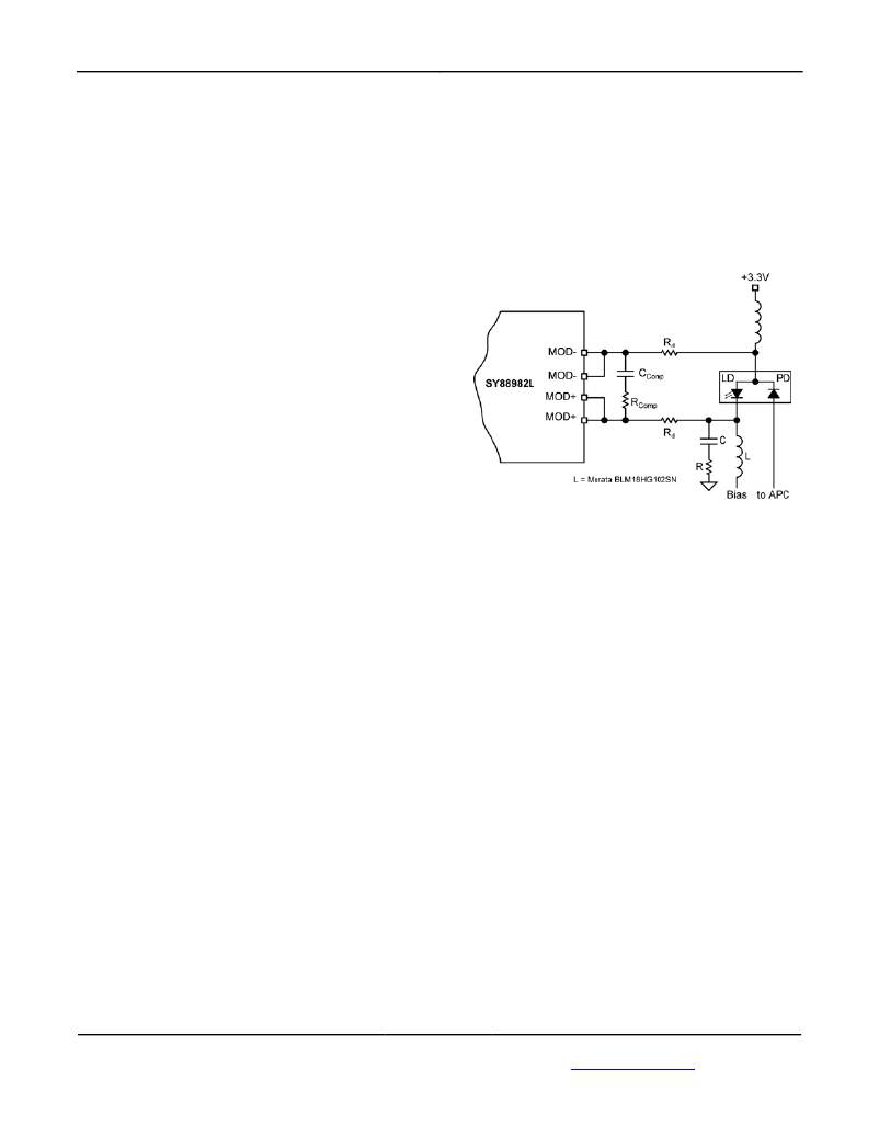
�signal� from� the� laser.� In� the� circuit� shown� in� Figure� 3,�
�the� RC� compensation� network� across� the� driver�
�SY88982AL�
�outputs� (MOD+� and� MOD-)� allows� the� user� R� d� =�
�10� ?.� The� optical� eye� diagrams� at� data� rates� of�
�155Mbps/622Mbps/1.25Gbps/2.5Gbps,� shown� in�
�“Functional� Characteristics”� section,� are� all� obtained�
�with� the� same� circuit� using� R� d� =� 10� ?,� R� Comp� =� 100� ?,�
�and� C� Comp� =� 3pF.� The� compensation� network� may�
�change� from� one� board� to� another� and� from� one�
�type� of� laser� to� another.� An� additional� compensation�
�network� (RC)� can� be� added� at� the� laser� cathode� for�
�further� compensation� and� eye� smoothing.�
�Figure� 3.� Laser� DC-Coupled�
�AC-Coupling�
�When� trying� to� AC� couple� the� laser� to� the� driver,� the�
�headroom� of� the� driver� is� no� longer� a� problem� since�
�it� is� DC� isolated� from� the� laser� with� the� coupling�
�capacitor.� At� the� output,� the� headroom� of� the� driver�
�is� determined� by� the� pull-up� network.� In� Figure� 4,� the�
�modulation� current� out� of� the� driver� is� split� between�
�the� pull-up� network� and� the� laser.� If,� for� example,� the�
�total� pull-up� resistor� is� twice� the� sum� of� the� damping�
�resistor� and� laser� equivalent� series� resistance,� only�
�two� thirds� (2/3)� of� the� modulation� current� will� be�
�used� by� the� laser.� So,� to� keep� most� of� the�
�modulation� current� going� through� the� laser,� the� total�
�pull-up� resistor� must� be� kept� as� high� as� possible.�
�One� solution� consists� in� using� an� inductor� alone� as�
�pull-up,� presenting� a� high� impedance� path� for� the�
�?�
�modulation� current� and� zero� ohm� (0� )� path� for� the�
�DC� current� offering� a� headroom� of� the� driver� equal�
�to� V� CC� and� almost� all� the� modulation� current� goes�
�into� the� laser.� The� inductor� alone� will� cause� signal�
�distortion,� and,� to� improve� that,� a� combination� of�
�resistors� and� inductors� can� be� used� (as� shown� on�
�Figure� 4).� In� this� case,� the� headroom� of� the� driver� is�
�V� CC� -R1� x� α� I� MOD� ,� where� α� I� MOD� is� the� portion� of� the�
�modulation� current� that� goes� through� the� pull-up�
�network.�
�When� the� laser� is� AC-coupled� to� the� driver,� the�
�coupling� capacitor� creates� a� low-frequency� cutoff� in�
�the� circuit,� and� its� value� must� be� chosen� as� large� as�
�December� 2009�
�8�
�M9999-121009-A�
�hbwhelp@micrel.com� or� (408)� 955-1690�
�相关PDF资料 |
PDF描述 |
|---|---|
| CAT28LV256G25 | IC EEPROM 256KBIT 250NS 32PLCC |
| ASC25DRYI-S13 | CONN EDGECARD 50POS .100 EXTEND |
| T86C226M6R3EASS | CAP TANT 22UF 6.3V 20% 2312 |
| RCC60DRAH-S734 | CONN EDGECARD 120PS .100 R/A PCB |
| LTC4223IDHD-1#PBF | IC CNTRLR HOT SWAP DUAL 16-DFN |
相关代理商/技术参数 |
参数描述 |
|---|---|
| SY88983V | 制造商:MICREL 制造商全称:Micrel Semiconductor 功能描述:3.3V/5V 3.2Gbps CML LOW-POWER LIMITING POST AMPLIFIER w/TTL SD |
| SY88983VKG | 功能描述:限幅放大器 3.3V-5V 3.2 Gbps CML Post Amp:1xSD gain/1xTC/10 pin MSOP/bulk (I Temp, Green) RoHS:否 制造商:Micrel 输入电压范围(最大值):3.6 V 工作电源电压:3.3 V 电源电流:40 mA 工作温度范围:- 40 C to + 85 C 封装 / 箱体:MSOP-10 封装:Tube |
| SY88983VKG TR | 功能描述:限幅放大器 3.3V-5V 3.2 Gbps CML Post Amp: 1xSD gain/1xTC/10 pin MSOP/ PbSn/ T+R (I Temp, Green) RoHS:否 制造商:Micrel 输入电压范围(最大值):3.6 V 工作电源电压:3.3 V 电源电流:40 mA 工作温度范围:- 40 C to + 85 C 封装 / 箱体:MSOP-10 封装:Tube |
| SY88983VKI | 功能描述:IC AMP POST 5/3.3V TTL SD 10MSOP RoHS:否 类别:集成电路 (IC) >> 线性 - 放大器 - 专用 系列:- 产品培训模块:Lead (SnPb) Finish for COTS Obsolescence Mitigation Program 标准包装:60 系列:- 类型:可变增益放大器 应用:CATV 安装类型:表面贴装 封装/外壳:20-WQFN 裸露焊盘 供应商设备封装:20-TQFN-EP(5x5) 包装:托盘 |
| SY88983VKI TR | 功能描述:IC AMP POST 5/3.3V TTL SD 10MSOP RoHS:否 类别:集成电路 (IC) >> 线性 - 放大器 - 专用 系列:- 产品培训模块:Lead (SnPb) Finish for COTS Obsolescence Mitigation Program 标准包装:60 系列:- 类型:可变增益放大器 应用:CATV 安装类型:表面贴装 封装/外壳:20-WQFN 裸露焊盘 供应商设备封装:20-TQFN-EP(5x5) 包装:托盘 |
发布紧急采购,3分钟左右您将得到回复。