- 您现在的位置:买卖IC网 > PDF目录98150 > SY89221UMG (MICREL INC) 89221 SERIES, LOW SKEW CLOCK DRIVER, 15 TRUE OUTPUT(S), 0 INVERTED OUTPUT(S), PQFP64 PDF资料下载
参数资料
| 型号: | SY89221UMG |
| 厂商: | MICREL INC |
| 元件分类: | 时钟及定时 |
| 英文描述: | 89221 SERIES, LOW SKEW CLOCK DRIVER, 15 TRUE OUTPUT(S), 0 INVERTED OUTPUT(S), PQFP64 |
| 封装: | LEAD FREE, TQFP-64 |
| 文件页数: | 12/17页 |
| 文件大小: | 828K |
| 代理商: | SY89221UMG |
Micrel, Inc.
SY89221U
September 2006
4
M9999-092906-A
hbwhelp@micrel.com or (408) 955-1690
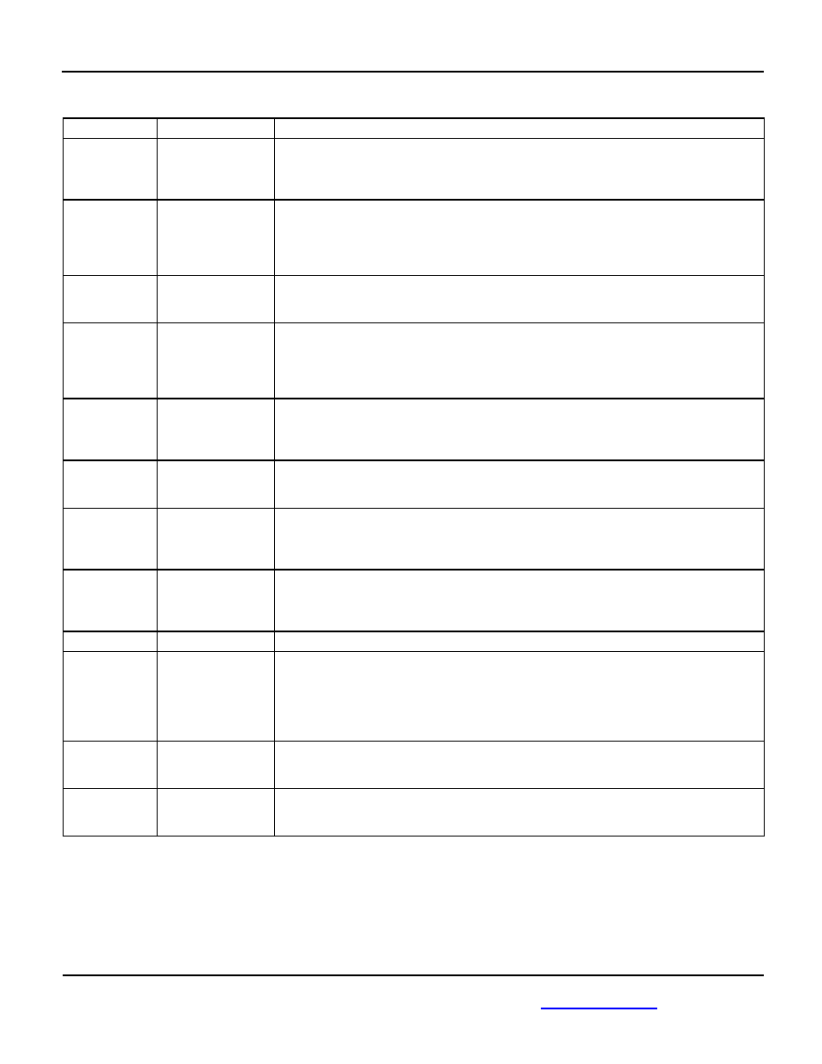
Pin Description
Pin Number
Pin Name
Pin Function
1, 2
3, 4
15, 16
17, 18
FSELA1, FSELA0
FSELB1, FSELB0
FSELC1, FSELC0
FSELD1, FSELD0
Single-Ended Inputs: These TTL/CMOS inputs select the divide ratio for each of the four
banks of outputs. Note that each of these inputs is internally connected to a 25k pull-up
resistor and will default to a logic HIGH state if left open. The input-switching threshold is
VCC/2.
5, 8,
11, 14
IN0, /IN0
IN1, /IN1
Differential Inputs: These input pairs are the differential signal inputs to the device. They
accept AC- or DC-coupled signals as small as 100mV. The input pairs internally
terminate to a VT pin through 50. Note that these inputs will default to an indeterminate
state if left open. Please refer to the “Input Interface Applications” section for more
details.
6, 12
VT0, VT1
Input Termination Center-Tap: Each side of a differential input pair terminates to a VT
pin. The VT pin provides a center-tap to a termination network for maximum interface
flexibility. See “ Input Interface Applications” section for more details.
7,
13
VREF-AC0,
VREF-AC1
Reference Voltage: These outputs bias to VCC–1.2V. They are used for AC-coupling
inputs IN and /IN. Connect VREF-AC directly to the corresponding VT pin. Bypass with
0.01F low ESR capacitor to VCC. Due to limited drive capability, the VREF-AC pin is
only intended to drive its respective VT pin. Maximum sink/source current is ±1.5mA.
Please refer to the “Input Interface Applications” section for more details.
9
/MR
Single-Ended Input: This TTL/CMOS-compatible master reset function asynchronously
sets the true outputs LOW, complimentary outputs HIGH, and holds them in that state as
long as /MR remains LOW. This input is internally connected to a 25k pull-up resistor
and will default to logic HIGH state if left open. The input-switching threshold is VCC/2.
10
CLK_SEL
Single-Ended Input: This TTL/CMOS-compatible input selects the inputs to the
multiplexer. Note that this input is internally connected to a 25k pull-up resistor and will
default to logic HIGH state if left open. The input-switching threshold is VCC/2.
20, 25, 30, 33,
40
41, 48, 50, 55,
62
VCC
Positive Power Supply. Bypass with a 0.1F||0.01F low ESR capacitor as close to VCC
pin as possible.
21, 22
23, 24
26, 27
28, 29
/QC0, QC0
/QC1, QC1
/QC2, QC2
/QC3, QC3
Bank C LVPECL differential output pairs controlled by FSELC0 and FSELC1. Refer to
“Function Table” for details. Unused output pairs may be left open. Each output is
designed to drive 800mV into 50 terminated to VCC – 2V.
31
NC
No connect.
34, 35,
36, 37
38, 39,
42, 43
44, 45,
46, 47
/QD0, QD0
/QD1, QD1
/QD2, QD2
/QD3, QD3
/QD4, QD4
/QD5, QD5
Bank D LVPECL differential output pairs controlled by FSELD0 and FSELD1. Refer to
“Function Table” for details. Unused output pairs may be left open. Each output is
designed to drive 800mV into 50 terminated to VCC – 2V.
51, 52
53, 54
/QA0, QA0
/QA1, QA1
Bank A LVPECL differential output pairs controlled by FSELA0 and FSELA1. Refer to
“Function Table” for details. Unused output pairs may be left open. Each output is
designed to drive 800mV into 50 terminated to VCC – 2V.
56, 57
58, 59
60, 61
/QB0, QB0
/QB1, QB1
/QB2, QB2
Bank B LVPECL differential output pairs controlled by FSELB0 and FSELB1. Refer to
“Function Table” for details. Unused output pairs may be left open. Each output is
designed to drive 800mV into 50 terminated to VCC – 2V.
相关PDF资料 |
PDF描述 |
|---|---|
| SY89231UMG | 89231 SERIES, LOW SKEW CLOCK DRIVER, 1 TRUE OUTPUT(S), 0 INVERTED OUTPUT(S), QCC16 |
| SY89297UMG | ACTIVE DELAY LINE, QCC24 |
| SY89464UMYTR | 89464 SERIES, LOW SKEW CLOCK DRIVER, 10 TRUE OUTPUT(S), 0 INVERTED OUTPUT(S), QCC44 |
| SY89464UMY | 89464 SERIES, LOW SKEW CLOCK DRIVER, 10 TRUE OUTPUT(S), 0 INVERTED OUTPUT(S), QCC44 |
| SY89467UHYTR | 89467 SERIES, LOW SKEW CLOCK DRIVER, 20 TRUE OUTPUT(S), 0 INVERTED OUTPUT(S), PQFP64 |
相关代理商/技术参数 |
参数描述 |
|---|---|
| SY89222L | 制造商:MICREL 制造商全称:Micrel Semiconductor 功能描述:3.3V DUAL TTL-to-DIFFERENTIAL PECL TRANSLATOR |
| SY89222LMG TR | 功能描述:转换 - 电压电平 3.3V Ultrasmall Dual LVTTL-to-LVPECL Translator (I Temp, Green) RoHS:否 制造商:Micrel 类型:CML/LVDS/LVPECL to LVCMOS/LVTTL 传播延迟时间:1.9 ns 电源电流:14 mA 电源电压-最大:3.6 V 电源电压-最小:3 V 最大工作温度:+ 85 C 安装风格:SMD/SMT 封装 / 箱体:MLF-8 |
| SY89222LMGTR | 制造商:Micrel Inc 功能描述: |
| SY89222LMG-TR | 功能描述:Mixed Signal Translator Unidirectional 1 Circuit 2 Channel 8-MLF? (2x2) 制造商:microchip technology 系列:SY89 包装:剪切带(CT) 零件状态:有效 转换器类型:混合信号 通道类型:单向 电路数:1 每个电路的通道数:2 电压 - VCCA:- 电压?- VCCB:- 输入信号:TTL 输出信号:PECL 输出类型:差分 数据速率:- 工作温度:-40°C ~ 85°C(TA) 特性:- 安装类型:表面贴装 封装/外壳:8-VFDFN 裸露焊盘,8-MLF? 供应商器件封装:8-MLF?(2x2) 标准包装:1 |
| SY89222LMI TR | 功能描述:IC TRANSLATOR DUAL 3.3V 8-MLF RoHS:否 类别:集成电路 (IC) >> 逻辑 - 变换器 系列:SY89 产品培训模块:Lead (SnPb) Finish for COTS Obsolescence Mitigation Program 标准包装:100 系列:- 逻辑功能:变换器,双向 位数:2 输入类型:CMOS 输出类型:CMOS 数据速率:16Mbps 通道数:2 输出/通道数目:1 差分 - 输入:输出:无/无 传输延迟(最大):15ns 电源电压:1.65 V ~ 5.5 V 工作温度:-40°C ~ 85°C 封装/外壳:10-UFQFN 供应商设备封装:10-UTQFN(1.4x1.8) 包装:管件 |
发布紧急采购,3分钟左右您将得到回复。