- 您现在的位置:买卖IC网 > PDF目录98152 > TA2002FN 0.05 W, 2 CHANNEL, AUDIO AMPLIFIER, PDSO24 PDF资料下载
参数资料
| 型号: | TA2002FN |
| 元件分类: | 音频/视频放大 |
| 英文描述: | 0.05 W, 2 CHANNEL, AUDIO AMPLIFIER, PDSO24 |
| 封装: | SSOP-24 |
| 文件页数: | 15/18页 |
| 文件大小: | 458K |
| 代理商: | TA2002FN |
TA2002F / FN
2002-10-30
6
In controlling the F / R SW with voltage source, it is applied as follows;
Forward mode: 0.8V~V17 (RF OUT)
Reverse mode: 0.15V~0.35V
(4) PRE SW
The terminal of PRE SW (pin(18)) should not be applied to higher voltage than V17 (RF out), because ripple
filter circuit supplies the PRE SW circuit with power source. And this terminal can't be connected with GND
line directly, because the PRE SW circuit doesn't operate normally.
In case of preamplifier on-mode, this terminal should be opened or connected with GND line through a resister
(R ≥ 10k).
It is advised to connect a external resistor (R4 = 100~330k) and capacitor (C4≒1F), in order to reduce a pop
sound in switchover between PRE SW on / off mode (see Fig.2). As for the constants, select the optimum one
depending on each a set carefully.
In controlling the PRE SW with voltage source, it is applied as follows;
Preamplifier on-mode: 0.1~0.5V
Preamplifier off-mode: 1.0V~ V17 (RF OUT)
(5) NF resistor of preamplifier
The NF resistor (R = 39k; see the test circuit) should be connected, to reduce a pop sound.
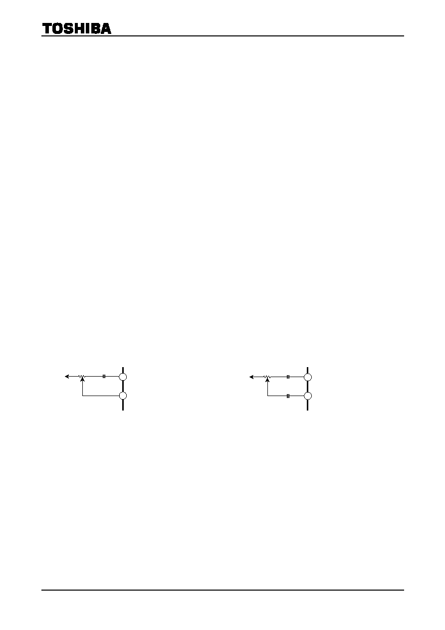
(6) Input of power amplifier
In case that the volume of power amplifier is less than 10k, it can be connected with power amplifier directly
as Fig.3-1. In case more than 10k, it is necessary to insert the coupling capacitor between volume and PW IN
terminal as Fig.3-2. In case that DC current or DC voltage is applied to the terminal of PW IN, the internal
circuit has unbalance and the power amplifier doesn't operate normally.
Fig.3
-1 Volume connection (1)
(R ≤ 10k)
Fig.3
-2 Volume connection (2)
(R > 10k)
PRE OUTA
5
6 PW INA
VREF
PRE OUTA
5
PW INA
VREF
6
相关PDF资料 |
PDF描述 |
|---|---|
| TA2002F | 0.05 W, 2 CHANNEL, AUDIO AMPLIFIER, PDSO24 |
| TA2003FG | AM/FM, AUDIO SINGLE CHIP RECEIVER, PDSO16 |
| TA2003PG | AM/FM, AUDIO SINGLE CHIP RECEIVER, PDIP16 |
| TA2003P | AUDIO SINGLE CHIP RECEIVER, PDIP16 |
| TA2003F | AUDIO SINGLE CHIP RECEIVER, PDSO16 |
相关代理商/技术参数 |
参数描述 |
|---|---|
| TA2003 | 制造商:UTC-IC 制造商全称:UTC-IC 功能描述:AM/FM RADIO IC |
| TA2003FG | 制造商:Toshiba America Electronic Components 功能描述: |
| TA2003P | 制造商:TOSHIBA 制造商全称:Toshiba Semiconductor 功能描述:AM/FM RADIO IC |
| TA2003P(M) | 制造商:Toshiba America Electronic Components 功能描述: |
| TA2003PG | 制造商:TOSHIBA 制造商全称:Toshiba Semiconductor 功能描述:AM / FM Radio IC |
发布紧急采购,3分钟左右您将得到回复。