- 您现在的位置:买卖IC网 > PDF目录98154 > TA7628P 0.6 W, 1 CHANNEL, AUDIO AMPLIFIER, PDIP16 PDF资料下载
参数资料
| 型号: | TA7628P |
| 元件分类: | 音频/视频放大 |
| 英文描述: | 0.6 W, 1 CHANNEL, AUDIO AMPLIFIER, PDIP16 |
| 封装: | 0.300 INCH, 2.54 MM PITCH, PLASTIC, DIP-16 |
| 文件页数: | 6/12页 |
| 文件大小: | 478K |
| 代理商: | TA7628P |
TA7628P/HP
2002-03-05
3
RB = 220 k at VCC = 7.5 V
RB = 150 k at VCC = 9 V
4.
Precaution of preamplifier
(1)
It is better that the coupling capacitor between the volume and the output of preamplifier is small.
Recommended value: C = 0.47 F
(2)
In recording mode, the signal source resistance must be more than 1 k for ALC (Automatic Level
Control) operation. When this resistance is small, the ALC range becomes narrow.
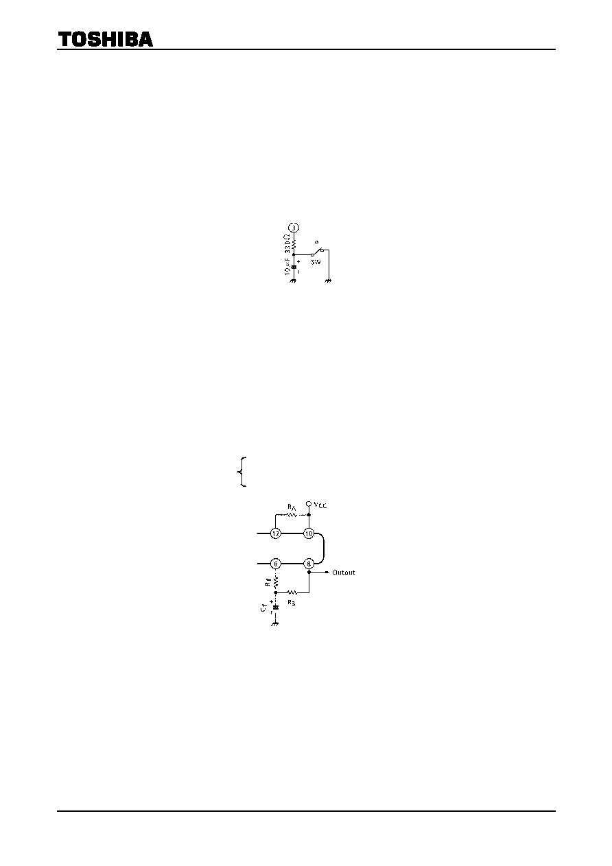
5.
Buffer amplifier
When the output signal is clipped in the buffer amplifier, this signal returns to preamplifier and influences
to make THD bad.
To prevent this, in playback mode, the buffer amplifier is recommended to be cut-off by terminating the
output terminal to GND directly or by terminating the feedback terminal to GND through 330 or less
than this shown in Figure 2.
Figure 2
6.
Power amplifier
(1)
In case of the battery use (VCC ≤ 6 V), this IC is happen to oscillate (blocking oscillation) when the
impedance of power supply is high.
In this case, it is recommended to insert the resistance RA of 500 ~1 k between pin 10 and pin 12
(VCC~Filter II). By this method, this IC becomes very stable. But the output DC voltage is not center
by the influence of RA. Then the output wave shape is not symmetrical clipping wave and the
maximum output voltage is reduced. So we recommend to insert the other resistance RB between
pin 6 and pin 8 for compensating the output DC voltage.
(2)
When you use this IC at the supply voltage of more than 6 V, it is better to insert the resistance RB
for compensating output DC voltage. (Figure 3)
The recommended value:
Figure 3
(3)
The output coupling capacitance and bootstrap capacitance is better to be large because of getting the
maximum output power.
(4)
On the PC board, the interval between VCC and GND is better to be large.
相关PDF资料 |
PDF描述 |
|---|---|
| TA7630P | 2 CHANNEL(S), TONE CONTROL CIRCUIT, PDIP16 |
| TA76432FR(TE12L) | 1-OUTPUT THREE TERM VOLTAGE REFERENCE, 1.26 V, PSSO3 |
| TA76432F(TE12L) | 1-OUTPUT THREE TERM VOLTAGE REFERENCE, 1.26 V, PSSO3 |
| TA76432FR | 1-OUTPUT THREE TERM VOLTAGE REFERENCE, 1.26 V, PSSO3 |
| TA76432F | 1-OUTPUT THREE TERM VOLTAGE REFERENCE, 1.26 V, PSSO3 |
相关代理商/技术参数 |
参数描述 |
|---|---|
| TA7629P | 制造商:未知厂家 制造商全称:未知厂家 功能描述:CD/TA7629P 是单通道杜比降噪电路,其内部设有杜比B 型降噪系统所需的放大器和方式开关。 |
| TA7630P | 制造商:Panasonic Industrial Company 功能描述:IC |
| TA7630PG | 制造商:Toshiba America Electronic Components 功能描述:Volume/Balance/Tone DC Control IC 16-Pin DIP |
| TA7639P(CN) | 制造商:未知厂家 制造商全称:未知厂家 功能描述:TA7639P 由两个通道的前置放大器、录音放大器和耳机放大器组成. |
| TA7640 | 制造商:UTC-IC 制造商全称:UTC-IC 功能描述:AM/FM IF PROCESSOR |
发布紧急采购,3分钟左右您将得到回复。