- 您现在的位置:买卖IC网 > PDF目录98157 > TA8700AN AUDIO/VIDEO DEMODULATOR, PDIP20 PDF资料下载
参数资料
| 型号: | TA8700AN |
| 元件分类: | 接收器 |
| 英文描述: | AUDIO/VIDEO DEMODULATOR, PDIP20 |
| 封装: | 0.300 INCH, 1.78 MM PITCH, PLASTIC, SDIP-20 |
| 文件页数: | 16/17页 |
| 文件大小: | 423K |
| 代理商: | TA8700AN |
TA8700AN
2001-05-10
8
TEST CONDITIONS
Note 1: Input sensitivity
PIF input (Pin 4) : fo=58.75MHz, fm=15.75kHz, 30% AM, 84dBV.
Gradually reduce the input level. Measure the input level when the detection output at video output (Pin
15-a) will be 3dB.
Note 2: Maximum input level
PIF input (Pin 4) : Input same as Note 1.
Gradually raise the input level. Measure the input level when the detection output at video output (Pin 15-a)
is at the noise inverter threshold.
Note 3: Differential gain / Differential phase
PIF input (Pin 4) : fo=58.75MHz, Standard television signal (V / S=10 : 4 ramp waveform), 87.5%
AM, 84dBV.
IF AGC=Free.
Measure the differential gain and differential phase with a vector scope. (Pin 15-b)
Note 4: No-signal output level
PIF input (Pin 4) : No input. 2nd AGC terminal (Pin 1) : GND, Measure DC voltage at video output Pin 15-a).
Note 5: Sync. Tip level
PIF input (Pin 4) : Input same as Note 3. Measure Sync. Tip DC voltage at video output (Pin 15-b).
Note 6: Video output amplitude
PIF input (Pin 4) : Input same as Note 3. Measure amplitude level at video output (Pin 15-b).
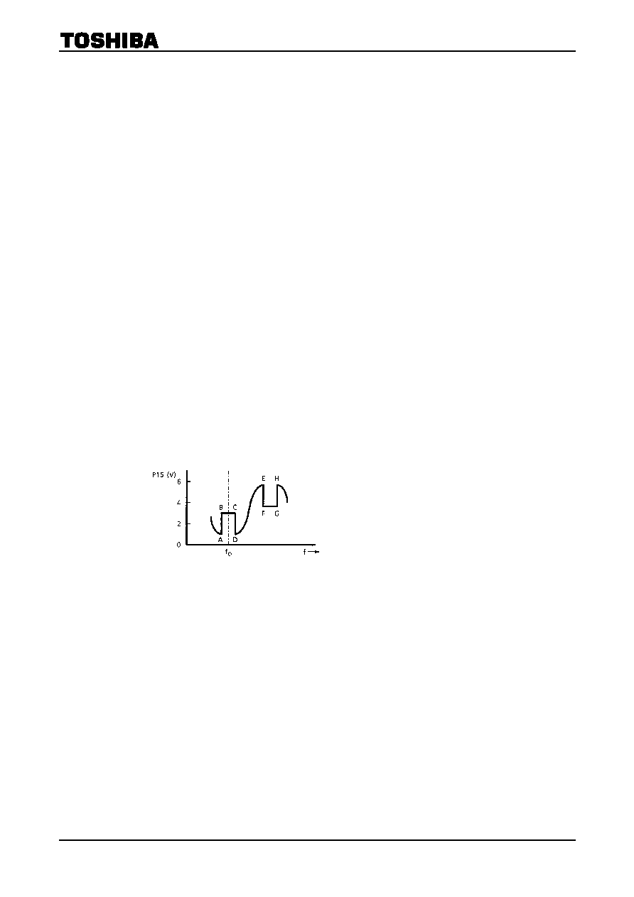
Note 7: Noise inverter
PIF input (Pin 4) : fo=57~65MHz (Sweep Signal), 84dBV.
Connect monitor scope to video output (Pin 15-b).
Measure the 2nd AGC terminal (Pin 1) voltage and fix the terminal to that voltage using the external power
supply.
Then, 2nd AGC Voltage variable when a waveform like that in the accompanying diagram is output.
AD: Black noise inverter level.
BC: Black noise clamp level.
EH: White noise inverter level.
FG: White noise clamp level.
相关PDF资料 |
PDF描述 |
|---|---|
| TA8701AN | AUDIO/VIDEO DEMODULATOR, PDIP24 |
| TA8703S | SPECIALTY CONSUMER CIRCUIT, PSIP12 |
| TA8712N | SPECIALTY CONSUMER CIRCUIT, PDIP20 |
| TA8720AN | SPECIALTY CONSUMER CIRCUIT, PDIP30 |
| TA8725AN | SPECIALTY CONSUMER CIRCUIT, PDIP56 |
相关代理商/技术参数 |
参数描述 |
|---|---|
| TA8701AN | 制造商:TOSHIBA 制造商全称:Toshiba Semiconductor 功能描述:PIF/SIF + ATT IC FOR TV/VTR |
| TA8703 | 制造商:TOSHIBA 制造商全称:Toshiba Semiconductor 功能描述:QUASI-SIF SYSTEM FOR TV |
| TA8703S | 制造商:Panasonic Industrial Company 功能描述:IC |
| TA8710 | 制造商:TOSHIBA 制造商全称:Toshiba Semiconductor 功能描述:SIF CONVERTER FOR TV AND VTR |
| TA8710S | 制造商:Panasonic Industrial Company 功能描述:IC |
发布紧急采购,3分钟左右您将得到回复。