- 您现在的位置:买卖IC网 > PDF目录98158 > TAS3204PAGR (TEXAS INSTRUMENTS INC) SPECIALTY CONSUMER CIRCUIT, PQFP64 PDF资料下载
参数资料
| 型号: | TAS3204PAGR |
| 厂商: | TEXAS INSTRUMENTS INC |
| 元件分类: | 消费家电 |
| 英文描述: | SPECIALTY CONSUMER CIRCUIT, PQFP64 |
| 封装: | GREEN, PLASTIC, TQFP-64 |
| 文件页数: | 21/76页 |
| 文件大小: | 1224K |
| 代理商: | TAS3204PAGR |
第1页第2页第3页第4页第5页第6页第7页第8页第9页第10页第11页第12页第13页第14页第15页第16页第17页第18页第19页第20页当前第21页第22页第23页第24页第25页第26页第27页第28页第29页第30页第31页第32页第33页第34页第35页第36页第37页第38页第39页第40页第41页第42页第43页第44页第45页第46页第47页第48页第49页第50页第51页第52页第53页第54页第55页第56页第57页第58页第59页第60页第61页第62页第63页第64页第65页第66页第67页第68页第69页第70页第71页第72页第73页第74页第75页第76页
SLES197C – APRIL 2007 – REVISED MARCH 2011
www.ti.com
Given the following example MCU data or program block (must be a multiple of 4 bytes for these blocks):
0x10 0x20 0x30 0x40 0x50 0x60 0x70 0x80
The checksum = 0x10 + 0x20 + 0x30 + 0x30 + 0x40 + 0x50 + 0x60 + 0x70 + 0x80 = 0x240, so
the values put in the checksum fields are MS byte = 0x02 and LS byte = 0x40.
If the checksum is >FFFFh, then the 2-byte checksum field is the least-significant 2 bytes.
For example, if the checksum is 0x1D 45B6, the checksum field is MS byte = 0x45 and LS byte = 0xB6.
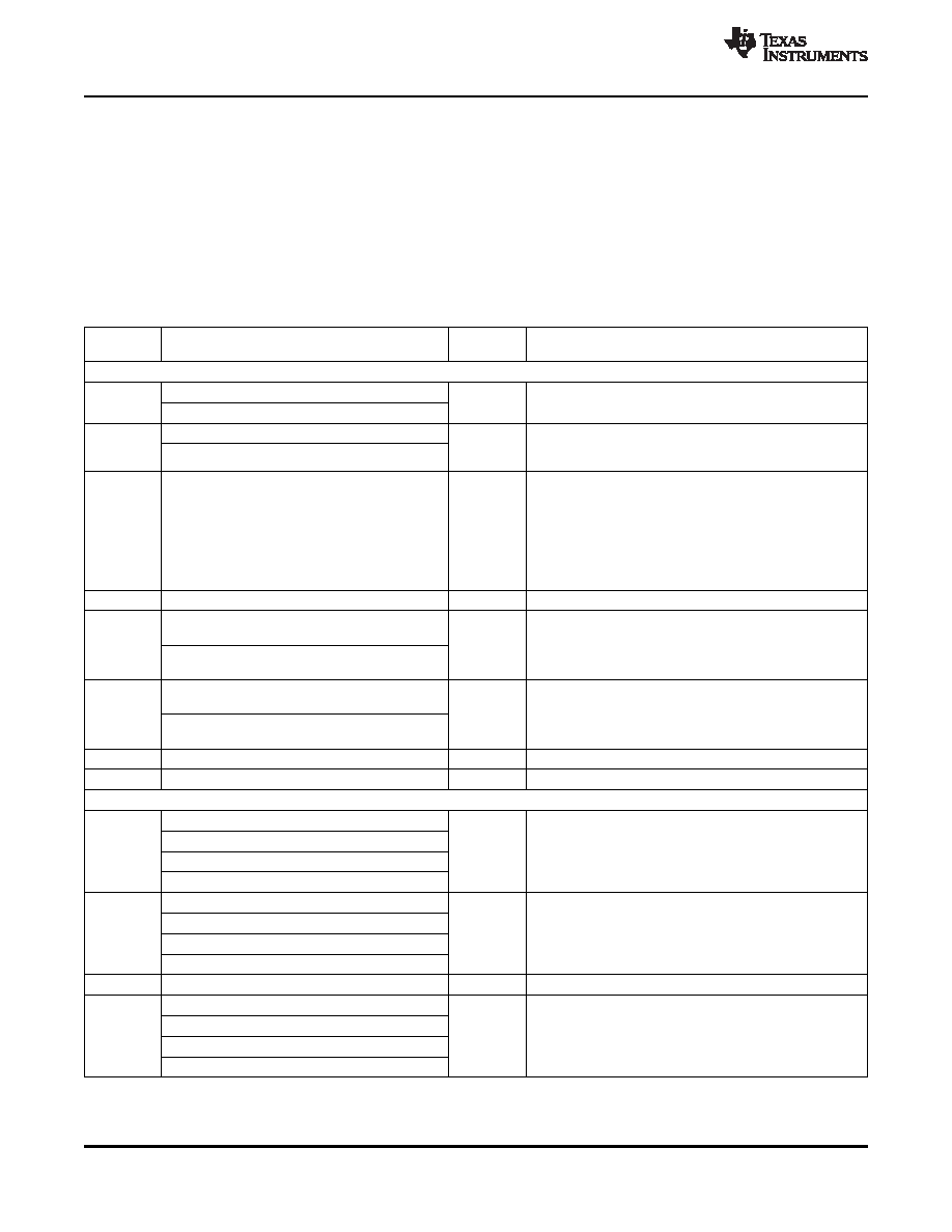
Table 8-1. TAS3204 Master I2C Memory Block Structures
STARTING
DATA BLOCK FORMAT
SIZE
NOTES
BYTE
12-Byte Header Block
Checksum code Most Significant Byte
Checksum of bytes 2 through N + 12.
0
2 Bytes
If this is a termination header, this value is 00 00
Checksum code Least Significant Byte
Header ID byte 1 = 0x00
Must be 0x001F for the TAS3204 to load as part of
2
2 Bytes
initialization. Any other value terminates the initialization
Header ID byte 2 = 0x1F
memory load sequence.
0x00 – MCU program memory - or - termination header
0x01 – MCU external data memory
0x02 – Audio DSP core program memory
0x03 – Audio DSP core coefficient memory
4
Memory to be loaded
1 Byte
0x04 – Audio DSP core data memory
0x05–06 – Audio DSP upper program memory
0x07 – Audio DSP Upper Coefficient Memory
0x08–FF – Reserved for future expansion
5
0x00
1 Byte
Reserved
Start TAS3204 memory address Most Significant
Byte
6
2 Bytes
If this is a termination header, this value is 0000.
Start TAS3204 memory address Least Significant
Byte
Total number of bytes transferred Most Significant
Byte
12 + data bytes + last checksum bytes. If this is a
8
2 Bytes
termination header, this value is 0000.
Total number of bytes transferred Least
Significant Byte
10
0x00
1 Byte
Unused
11
0x00
1 Byte
Unused
Data Block for MCU Program or Data Memory (Following 12-Byte Header)
Data Byte 1 (LSB)
Data Byte 2
12
4 Bytes
MCU Bytes 1-4
Data Byte 3
Data byte 4 (MSB)
Data byte 5
Data byte 6
16
4 Bytes
MCU Bytes 5-8
Data byte 7
Data byte 8
Data byte 4×(Z – 1) + 1
Data byte 4×(Z – 1) + 2
N + 8
4 Bytes
MCU Bytes N-N+4
Data byte 4×(Z – 1) + 3
Data byte 4×(Z – 1) + 4 = N
28
Copyright 2007–2011, Texas Instruments Incorporated
I2C Control Interface
Product Folder Link(s): TAS3204
相关PDF资料 |
PDF描述 |
|---|---|
| TAS3204PAG | SPECIALTY CONSUMER CIRCUIT, PQFP64 |
| TAS3218IPZPR | SPECIALTY CONSUMER CIRCUIT, PQFP100 |
| TAS3218IPZP | SPECIALTY CONSUMER CIRCUIT, PQFP100 |
| TAS3218PZPR | SPECIALTY CONSUMER CIRCUIT, PQFP100 |
| TAS3218PZP | SPECIALTY CONSUMER CIRCUIT, PQFP100 |
相关代理商/技术参数 |
参数描述 |
|---|---|
| TAS3208 | 制造商:TI 制造商全称:Texas Instruments 功能描述:DIGITAL AUDIO PROCESSOR WITH ANALOG INTERFACE |
| TAS3208EVM | 功能描述:音频 IC 开发工具 TAS3208EVM Eval Mod RoHS:否 制造商:Texas Instruments 产品:Evaluation Kits 类型:Audio Amplifiers 工具用于评估:TAS5614L 工作电源电压:12 V to 38 V |
| TAS3208EVM-LC | 功能描述:音频 IC 开发工具 TAS3208 Low Cost EVM RoHS:否 制造商:Texas Instruments 产品:Evaluation Kits 类型:Audio Amplifiers 工具用于评估:TAS5614L 工作电源电压:12 V to 38 V |
| TAS3208IPZP | 功能描述:音频 DSP Dual Core Dig Aud Proc RoHS:否 制造商:Texas Instruments 工作电源电压: 电源电流: 工作温度范围: 安装风格: 封装 / 箱体: 封装:Tube |
| TAS3208IPZPR | 功能描述:音频 DSP Dual Core Dig Aud Proc RoHS:否 制造商:Texas Instruments 工作电源电压: 电源电流: 工作温度范围: 安装风格: 封装 / 箱体: 封装:Tube |
发布紧急采购,3分钟左右您将得到回复。