- 您现在的位置:买卖IC网 > PDF目录98161 > TAS5121DKDRE4 (TEXAS INSTRUMENTS INC) 100 W, 2 CHANNEL, AUDIO AMPLIFIER, PDSO36 PDF资料下载
参数资料
| 型号: | TAS5121DKDRE4 |
| 厂商: | TEXAS INSTRUMENTS INC |
| 元件分类: | 音频/视频放大 |
| 英文描述: | 100 W, 2 CHANNEL, AUDIO AMPLIFIER, PDSO36 |
| 封装: | GREEN, PLASTIC, HSSOP-36 |
| 文件页数: | 3/21页 |
| 文件大小: | 591K |
| 代理商: | TAS5121DKDRE4 |
TAS5121
SLES086A NOVEMBER 2003 REVISED MARCH 2004
www.ti.com
11
A digitally controlled dead-time circuit controls the
transitions between the high-side and low-side MOSFETs
to ensure that both devices in each half-bridge are not
conducting simultaneously.
POWERING DOWN
For power down of the TAS5121, an opposite approach is
necessary. The RESET must be asserted LOW before the
valid PWM signal is removed.
PRECAUTION
The TAS5121 must always start up in the high-impedance
(Hi-Z) state. In this state, the bootstrap (BST) capacitor is
precharged by a resistor on each PWM output node to
ground. See the system configuration. This ensures that
the TAS5121 is ready for receiving PWM pulses, indicating
either HIGH- or LOW-side turnon after RESET is
de-asserted to the back end.
With the following pulldown resistor and BST capacitor
size, the BST charge time is:
C = 33 nF, R = 4.7 k
R
× C × 5 = 775.5 s
After GVDD has been applied, it takes approximately 800
s to fully charge the BST capacitor. During this time,
RESET must be kept low. After approximately 1 ms the
back end BST is charged and ready. RESET can now be
released if the PWM modulator is ready and is streaming
valid PWM signals to the device. Valid PWM signals are
switching PWM signals with a frequency between
350400 kHz. A constant HIGH level on the PWM+ forces
the high-side MOSFET ON until it eventually runs out of
BST capacitor energy. Putting the device in this condition
should be avoided.
In practice this means that the DVDD-to-PWM processor
(front-end) should be stable and initialization should be
completed before RESET is de-asserted to the TAS5121.
CONTROL I/O
Shutdown Pin: SD
The SD pin functions as an output pin and is intended for
protection-mode signaling to, for example, a controller or
other front-end device. The pin is open-drain with an
internal pullup resistor to DVDD.
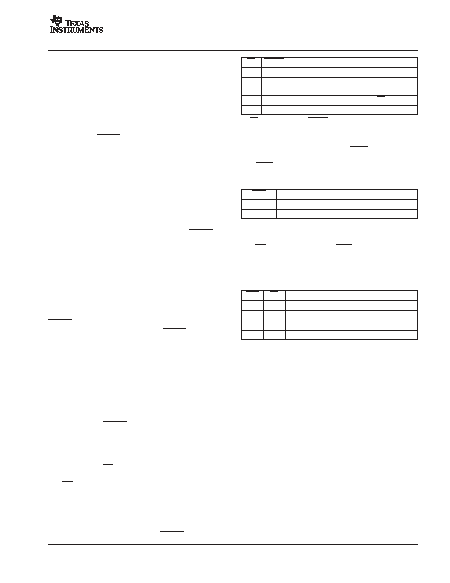
The logic output is, as shown in the following table, a
combination of the device state and RESET input:
SD
RESET
DESCRIPTION
0
Reserved
0
1
Device in protection mode, i.e., UVP and/or OC
and/or OT error
1(2)
0
Device set high-impedance (Hi-Z), SD forced high
1
Normal operation
(2) SD is pulled high when RESET is asserted low independent of chip
state (i.e., protection mode). This is desirable to maintain
compatibility with some TI PWM front ends.
Overtemperature Warning Pin: OTW
The OTW pin gives a temperature warning signal when
temperature exceeds the set limit. The pin is of the
open-drain type with an internal pullup resistor to DVDD.
OTW
DESCRIPTION
0
Junction temperature higher than 115
°C
1
Junction temperature lower than 115
°C
Overall Reporting
The SD pin, together with the OTW pin, gives chip state
information as described in Table 1.
Table 1. Error Signal Decoding
OTW
SD
DESCRIPTION
0
Overtemperature error (OTE)
0
1
Overtemperature warning (OTW)
1
0
Overcurrent (OC) or undervoltage (UVP) error
1
Normal operation, no errors/warnings
Chip Protection
The
TAS5121
protection
function
is
generally
implemented in a closed loop control system with, for
example, a system controller. The TAS5121 contains three
individual systems protecting the device against fault
conditions. All of the error events result in the output stage
being set in a high-impedance state (Hi-Z) for maximum
protection of the device and connected equipment.
The device can be recovered by toggling RESET low and
then high, after all errors are cleared. It is recommended
that if the error persists, the device is held in reset until user
intervention clears the error.
Overcurrent (OC) Protection
The device has individual current protection on both
high-side and low-side power stage FETs. The OC
protection works only with the demodulation filter present
at the output. See Filter Demodulation Design in the
Application Information section of the data sheet for design
constraints.
相关PDF资料 |
PDF描述 |
|---|---|
| TAS5121DKDR | 100 W, 2 CHANNEL, AUDIO AMPLIFIER, PDSO36 |
| TAS5121DKD | 100 W, 2 CHANNEL, AUDIO AMPLIFIER, PDSO36 |
| TAS5121IDKDE4 | 100 W, 2 CHANNEL, AUDIO AMPLIFIER, PDSO36 |
| TAS5121IDKDRE4 | 100 W, 2 CHANNEL, AUDIO AMPLIFIER, PDSO36 |
| TAS5121IDKDR | 100 W, 2 CHANNEL, AUDIO AMPLIFIER, PDSO36 |
相关代理商/技术参数 |
参数描述 |
|---|---|
| TAS5121I | 制造商:TI 制造商全称:Texas Instruments 功能描述:DIGITAL AMPLIIFIER POWER STAGE |
| TAS5121IDKD | 功能描述:音频放大器 Digital Amplifier Power Stage RoHS:否 制造商:STMicroelectronics 产品:General Purpose Audio Amplifiers 输出类型:Digital 输出功率: THD + 噪声: 工作电源电压:3.3 V 电源电流: 最大功率耗散: 最大工作温度: 安装风格:SMD/SMT 封装 / 箱体:TQFP-64 封装:Reel |
| TAS5121IDKDE4 | 功能描述:音频放大器 Digital Amplifier Power Stage RoHS:否 制造商:STMicroelectronics 产品:General Purpose Audio Amplifiers 输出类型:Digital 输出功率: THD + 噪声: 工作电源电压:3.3 V 电源电流: 最大功率耗散: 最大工作温度: 安装风格:SMD/SMT 封装 / 箱体:TQFP-64 封装:Reel |
| TAS5121IDKDR | 功能描述:音频放大器 Digital Amplifier Power Stage RoHS:否 制造商:STMicroelectronics 产品:General Purpose Audio Amplifiers 输出类型:Digital 输出功率: THD + 噪声: 工作电源电压:3.3 V 电源电流: 最大功率耗散: 最大工作温度: 安装风格:SMD/SMT 封装 / 箱体:TQFP-64 封装:Reel |
| TAS5121IDKDRE4 | 功能描述:音频放大器 Digital Amplifier Power Stage RoHS:否 制造商:STMicroelectronics 产品:General Purpose Audio Amplifiers 输出类型:Digital 输出功率: THD + 噪声: 工作电源电压:3.3 V 电源电流: 最大功率耗散: 最大工作温度: 安装风格:SMD/SMT 封装 / 箱体:TQFP-64 封装:Reel |
发布紧急采购,3分钟左右您将得到回复。