- 您现在的位置:买卖IC网 > PDF目录98162 > TAS5342DDVG4 (TEXAS INSTRUMENTS INC) 200 W, 2 CHANNEL, AUDIO AMPLIFIER, PDSO44 PDF资料下载
参数资料
| 型号: | TAS5342DDVG4 |
| 厂商: | TEXAS INSTRUMENTS INC |
| 元件分类: | 音频/视频放大 |
| 英文描述: | 200 W, 2 CHANNEL, AUDIO AMPLIFIER, PDSO44 |
| 封装: | GREEN, PLASTIC, HTSSOP-44 |
| 文件页数: | 2/29页 |
| 文件大小: | 866K |
| 代理商: | TAS5342DDVG4 |
第1页当前第2页第3页第4页第5页第6页第7页第8页第9页第10页第11页第12页第13页第14页第15页第16页第17页第18页第19页第20页第21页第22页第23页第24页第25页第26页第27页第28页第29页
www.ti.com
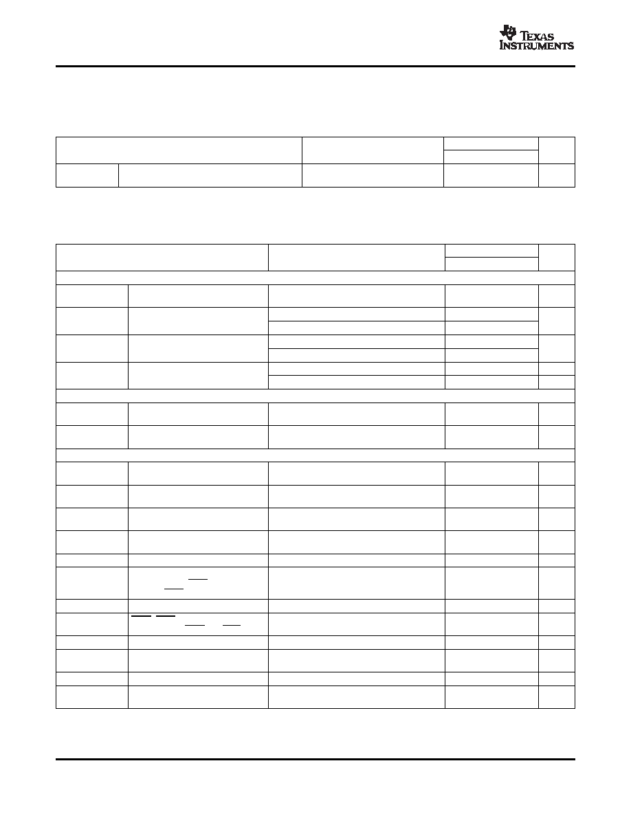
ELECTRICAL CHARACTERISTICS
SLAS557B – SEPTEMBER 2007 – REVISED OCTOBER 2007
AUDIO SPECIFICATIONS (PBTL) (continued)
Audio performance is recorded as a chipset consisting of a TAS5518 pwm processor (modulation index limited to 97.7%) and
a TAS5342 power stage. PCB and system configuraton are in accordance with recommended guidelines. Audio frequency =
1kHz, PVDD_x = 31.5 V, GVDD_x = 12 V, RL = 3 , fS = 384 kHz, ROC = 27 k, TC = 75°C, Output Filter: LDEM = 10 μH, CDEM
= 1.0 uF, unless otherwise noted.
TAS5342
PARAMETER
TEST CONDITIONS
UNIT
MIN
TYP
MAX
PO = 0 W, all half bridges
Pidle
Power dissipation due to idle losses (IPVDD_X)
2
W
switching(2)
(2)
Actual system idle losses are affected by core losses of output inductors.
PVDD_x = 31.5 V, GVDD_X = 12 V, VDD = 12 V, TC (Case temperature) = 25°C, fS = 384 kHz, unless otherwise specified.
TAS5342
PARAMETER
TEST CONDITIONS
UNIT
MIN
TYP
MAX
Internal Voltage Regulator and Current Consumption
Voltage regulator, only used as a
VREG
VDD = 12 V
3
3.3
3.6
V
reference node
Operating, 50% duty cycle
7.2
17
IVDD
VDD supply current
mA
Idle, reset mode
5.54
11
50% duty cycle
8
16
IGVDD_X
Gate supply current per half-bridge
mA
Reset mode
1
1.8
50% duty cycle, without output filter or load
16.6
25
mA
IPVDD_X
Half-bridge idle current
Reset mode, no switching
465
558
μA
Output Stage MOSFETs
Drain-to-source resistance, Low
RDSon,LS
TJ = 25°C, excludes metallization resistance,
80
89
m
Side
Drain-to-source resistance, High
RDSon,HS
TJ = 25°C, excludes metallization resistance,
80
89
m
Side
I/O Protection
Undervoltage protection limit,
Vuvp,G
9.5
V
GVDD_X
Vuvp,hyst
(1)
Undervoltage protection limit,
250
mV
GVDD_X
BSTuvpF
Puts device into RESET when BST
5.85
V
voltage falls below limit
BSTuvpR
Brings device out of RESET when
7
V
BST voltage rises above limit
OTW(1)
Overtemperature warning
115
125
135
°C
Temperature drop needed below
OTWHYST
(1)
OTW temp. for OTW to be inactive
25
°C
after the OTW event
OTE(1)
Overtemperature error threshold
145
155
165
°C
OTE-
OTE - OTW differential, temperature
30
°C
OTWdifferential
(1)
delta between OTW and OTE
OLPC
Overload protection counter
fS = 384 kHz
1.25
ms
Resistor—programmable, high-end,
IOC
Overcurrent limit protection
10.1
A
ROC = 27 k with 1 ms pulse
IOCT
Overcurrent response time
150
ns
tACTIVITY
Time for PWM activity detector to
Lack of transistion of any PWM input
13.2
μS
DETECTOR
activite when no PWM is present
(1)
Specified by design
10
Copyright 2007, Texas Instruments Incorporated
Product Folder Link(s): TAS5342
相关PDF资料 |
PDF描述 |
|---|---|
| TAS5342DDVRG4 | 200 W, 2 CHANNEL, AUDIO AMPLIFIER, PDSO44 |
| TAS5342DDVR | 200 W, 2 CHANNEL, AUDIO AMPLIFIER, PDSO44 |
| TAS5342DDV | 200 W, 2 CHANNEL, AUDIO AMPLIFIER, PDSO44 |
| TAS5342LADDV | 200 W, 2 CHANNEL, AUDIO AMPLIFIER, PDSO44 |
| TAS5342LDDVG4 | 100 W, 2 CHANNEL, AUDIO AMPLIFIER, PDSO44 |
相关代理商/技术参数 |
参数描述 |
|---|---|
| TAS5342DDVR | 功能描述:音频放大器 100W Class D Stereo Power Stage RoHS:否 制造商:STMicroelectronics 产品:General Purpose Audio Amplifiers 输出类型:Digital 输出功率: THD + 噪声: 工作电源电压:3.3 V 电源电流: 最大功率耗散: 最大工作温度: 安装风格:SMD/SMT 封装 / 箱体:TQFP-64 封装:Reel |
| TAS5342DDVRG4 | 功能描述:音频放大器 100W Class D Stereo Power Stage RoHS:否 制造商:STMicroelectronics 产品:General Purpose Audio Amplifiers 输出类型:Digital 输出功率: THD + 噪声: 工作电源电压:3.3 V 电源电流: 最大功率耗散: 最大工作温度: 安装风格:SMD/SMT 封装 / 箱体:TQFP-64 封装:Reel |
| TAS5342L | 制造商:TI 制造商全称:Texas Instruments 功能描述:100 W STEREO DIGITAL AMPLIFIER POWER STAGE |
| TAS5342LA | 制造商:TI 制造商全称:Texas Instruments 功能描述:100 W STEREO DIGITAL AMPLIFIER POWER STAGE |
| TAS5342LAADDVR | 制造商:Texas Instruments 功能描述:Class D Amplifier |
发布紧急采购,3分钟左右您将得到回复。