- 您现在的位置:买卖IC网 > PDF目录98163 > TAS5414TDKDMQ1 (TEXAS INSTRUMENTS INC) 116 W, 4 CHANNEL, AUDIO AMPLIFIER, PDSO36 PDF资料下载
参数资料
| 型号: | TAS5414TDKDMQ1 |
| 厂商: | TEXAS INSTRUMENTS INC |
| 元件分类: | 音频/视频放大 |
| 英文描述: | 116 W, 4 CHANNEL, AUDIO AMPLIFIER, PDSO36 |
| 封装: | GREEN, PLASTIC, HSSOP-36 |
| 文件页数: | 13/43页 |
| 文件大小: | 978K |
| 代理商: | TAS5414TDKDMQ1 |
第1页第2页第3页第4页第5页第6页第7页第8页第9页第10页第11页第12页当前第13页第14页第15页第16页第17页第18页第19页第20页第21页第22页第23页第24页第25页第26页第27页第28页第29页第30页第31页第32页第33页第34页第35页第36页第37页第38页第39页第40页第41页第42页第43页
www.ti.com
I
2C Bus Protocol
SLOS514A – FEBRUARY 2007 – REVISED JULY 2007
DESCRIPTION OF OPERATION (continued)
Select current limit (for 2- and for 4- loads). This allows optimal design of the filter inductor, and the use of
smaller gauge speaker wires for 4-
applications.
Select AM non-interference switching frequency
Select the function of OTW_CLIP pin
Enable or disable dc detect function with selectable threshold
Place channel in Hi-Z (switching stopped) mode (mute)
Select tweeter detect, set detect threshold and initiate function
Initiate open/short load diagnostic
Reset faults and return to normal switching operation from Hi-Z mode (unmute)
In addition to the standard SDA and SCL pins for the I2C bus, the TAS5414 and the TAS5424 include a single
pin that allows up to four devices to work together in a system with no additional hardware required for
communication or synchronization. The I2C_ADDR pin sets the device in master or slave mode and selects the
I2C address for that device. Tie I2C_ADDR to DGND for master, to 1.2 Vdc for slave 1, to 2.4 Vdc for slave 2,
and to D_BYP for slave 3. The OSC_SYNC pin is used to synchronize the internal clock oscillators and thereby
avoid beat frequencies. An external oscillator can also be applied to this pin for external control of the switching
frequency.
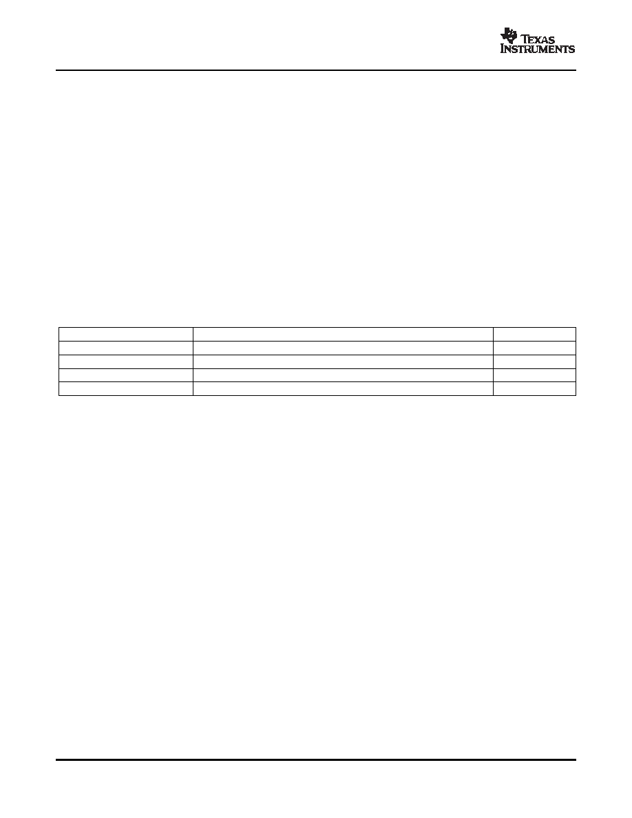
Table 2. Table 7. I2C_ADDR Pin Connection
DESCRIPTION
I2C_ADDR PIN CONNECTION
I2C ADDRESS
TAS5414/5424 0 (OSC MASTER)
To SGND pin
0xD8/D9
TAS5414/5424 1 (OSC SLAVE1)
35% DVDD (resistive voltage divider between D_BYP pin and SGND pin)(1)
0xDA/DB
TAS5414/5424 2 (OSC SLAVE2)
65% DVDD (resistive voltage divider between D_BYP pin and SGND pin)(1)
0xDC/DD
TAS5414/5424 3 (OSC SLAVE3)
To D_BYP pin
0xDE/DF
(1)
RI2C_ADDR with 5% or better tolerance is recommended.
The TAS5414 and TAS5424 have a bidirectional serial control interface that is compatible with the Inter IC (I2C)
bus protocol and supports 100-kbps data transfer rates for random and sequential write and read operations.
This is a slave-only device that does not support a multimaster bus environment or wait state insertion. The
control interface is used to program the registers of the device and to read device status.
The I2C bus employs two signals, SDA (data) and SCL (clock), to communicate between integrated circuits in a
system. Data is transferred on the bus serially, one bit at a time. The address and data are transferred in byte
(8-bit) format with the most-significant bit (MSB) transferred first. In addition, each byte transferred on the bus is
acknowledged by the receiving device with an acknowledge bit. Each transfer operation begins with the master
device driving a start condition on the bus and ends with the master device driving a stop condition on the bus.
The bus uses transitions on the data terminal (SDA) while the clock is HIGH to indicate a start and stop
conditions. A HIGH-to-LOW transition on SDA indicates a start, and a LOW-to-HIGH transition indicates a stop.
Normal data bit transitions must occur within the low time of the clock period. These conditions are shown in
Figure 16. The master generates the 7-bit slave address and the read/write (R/W) bit to open communication
with another device and then wait for an acknowledge condition. The TAS5414 and TAS5424 hold SDA LOW
during the acknowledge-clock period to indicate an acknowledgement. When this occurs, the master transmits
the next byte of the sequence. Each device is addressed by a unique 7-bit slave address plus R/W bit (1 byte).
All compatible devices share the same signals via a bidirectional bus using a wired-AND connection. An external
pullup resistor must be used for the SDA and SCL signals to set the HIGH level for the bus. There is no limit on
the number of bytes that can be transmitted between start and stop conditions. When the last word transfers, the
master generates a stop condition to release the bus.
20
相关PDF资料 |
PDF描述 |
|---|---|
| TAS5414TDKDRMQ1 | 116 W, 4 CHANNEL, AUDIO AMPLIFIER, PDSO36 |
| TAS5414TDKDMQ1G4 | 116 W, 4 CHANNEL, AUDIO AMPLIFIER, PDSO36 |
| TAS5414TDKDRMQ1G4 | 116 W, 4 CHANNEL, AUDIO AMPLIFIER, PDSO36 |
| TAS5504PAGRG4 | SPECIALTY CONSUMER CIRCUIT, PQFP64 |
| TAS5504PAGG4 | SPECIALTY CONSUMER CIRCUIT, PQFP64 |
相关代理商/技术参数 |
参数描述 |
|---|---|
| TAS5414TDKDMQ1G4 | 功能描述:音频放大器 4-Ch Auto Dig Amp RoHS:否 制造商:STMicroelectronics 产品:General Purpose Audio Amplifiers 输出类型:Digital 输出功率: THD + 噪声: 工作电源电压:3.3 V 电源电流: 最大功率耗散: 最大工作温度: 安装风格:SMD/SMT 封装 / 箱体:TQFP-64 封装:Reel |
| TAS5414TDKDQ1 | 功能描述:音频放大器 4-Ch Auto Dig Amp RoHS:否 制造商:STMicroelectronics 产品:General Purpose Audio Amplifiers 输出类型:Digital 输出功率: THD + 噪声: 工作电源电压:3.3 V 电源电流: 最大功率耗散: 最大工作温度: 安装风格:SMD/SMT 封装 / 箱体:TQFP-64 封装:Reel |
| TAS5414TDKDQ1G4 | 功能描述:音频放大器 4-Ch Auto Dig Amp RoHS:否 制造商:STMicroelectronics 产品:General Purpose Audio Amplifiers 输出类型:Digital 输出功率: THD + 噪声: 工作电源电压:3.3 V 电源电流: 最大功率耗散: 最大工作温度: 安装风格:SMD/SMT 封装 / 箱体:TQFP-64 封装:Reel |
| TAS5414TDKDRMQ1 | 功能描述:音频放大器 4-Ch Auto Dig Amp RoHS:否 制造商:STMicroelectronics 产品:General Purpose Audio Amplifiers 输出类型:Digital 输出功率: THD + 噪声: 工作电源电压:3.3 V 电源电流: 最大功率耗散: 最大工作温度: 安装风格:SMD/SMT 封装 / 箱体:TQFP-64 封装:Reel |
| TAS5414TDKDRMQ1G4 | 功能描述:音频放大器 4-Ch Auto Dig Amp RoHS:否 制造商:STMicroelectronics 产品:General Purpose Audio Amplifiers 输出类型:Digital 输出功率: THD + 噪声: 工作电源电压:3.3 V 电源电流: 最大功率耗散: 最大工作温度: 安装风格:SMD/SMT 封装 / 箱体:TQFP-64 封装:Reel |
发布紧急采购,3分钟左右您将得到回复。