- 您现在的位置:买卖IC网 > PDF目录10537 > TAS5711PHPR (Texas Instruments)IC AMP AUD DGTL 20W 2CH 48HTQFP PDF资料下载
参数资料
| 型号: | TAS5711PHPR |
| 厂商: | Texas Instruments |
| 文件页数: | 25/66页 |
| 文件大小: | 0K |
| 描述: | IC AMP AUD DGTL 20W 2CH 48HTQFP |
| 标准包装: | 1 |
| 类型: | D 类 |
| 输出类型: | 2 通道(立体声,2.1)或 4 通道(四路) |
| 在某负载时最大输出功率 x 通道数量: | 21W x 2 @ 8 欧姆 |
| 电源电压: | 8 V ~ 26 V |
| 特点: | 消除爆音,数字输入,I²C,I²S,静音,短路和热保护,关机,音量控制 |
| 安装类型: | 表面贴装 |
| 供应商设备封装: | 48-HTQFP(7x7) |
| 封装/外壳: | 48-TQFP 裸露焊盘 |
| 包装: | 标准包装 |
| 产品目录页面: | 860 (CN2011-ZH PDF) |
| 其它名称: | 296-25564-6 |
第1页第2页第3页第4页第5页第6页第7页第8页第9页第10页第11页第12页第13页第14页第15页第16页第17页第18页第19页第20页第21页第22页第23页第24页当前第25页第26页第27页第28页第29页第30页第31页第32页第33页第34页第35页第36页第37页第38页第39页第40页第41页第42页第43页第44页第45页第46页第47页第48页第49页第50页第51页第52页第53页第54页第55页第56页第57页第58页第59页第60页第61页第62页第63页第64页第65页第66页
7-BitSlave Address
R/
W
8-BitRegister Address(N)
A
8-BitRegisterDataFor
Address(N)
Start
Stop
SDA
SCL
7
6
5
4
3
2
1
0
7
6
5
4
3
2
1
0
7
6
5
4
3
2
1
0
7
6
5
4
3
2
1
0
A
8-BitRegisterDataFor
Address(N)
A
T0035-01
www.ti.com
SLOS600A – DECEMBER 2009 – REVISED AUGUST 2010
I
2C SERIAL CONTROL INTERFACE
The TAS5711 DAP has a bidirectional I2C interface that compatible with the I2C (Inter IC) bus protocol and
supports both 100-kHz and 400-kHz data transfer rates for single and multiple byte write and read operations.
This is a slave only device that does not support a multimaster bus environment or wait state insertion. The
control interface is used to program the registers of the device and to read device status.
The DAP supports the standard-mode I2C bus operation (100 kHz maximum) and the fast I2C bus operation
(400 kHz maximum). The DAP performs all I2C operations without I2C wait cycles.
General I2C Operation
The I2C bus employs two signals; SDA (data) and SCL (clock), to communicate between integrated circuits in a
system. Data is transferred on the bus serially one bit at a time. The address and data can be transferred in byte
(8-bit) format, with the most significant bit (MSB) transferred first. In addition, each byte transferred on the bus is
acknowledged by the receiving device with an acknowledge bit. Each transfer operation begins with the master
device driving a start condition on the bus and ends with the master device driving a stop condition on the bus.
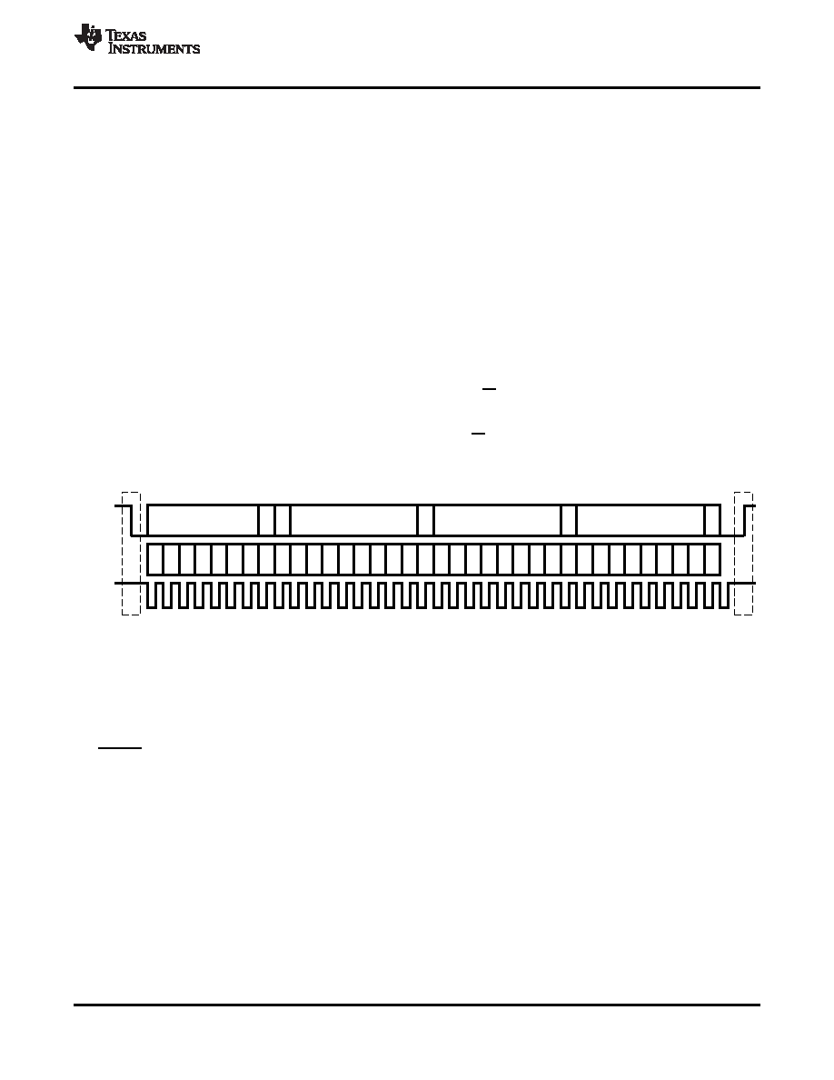
The bus uses transitions on the data pin (SDA) while the clock is high to indicate a start and stop conditions. A
high-to-low transition on SDA indicates a start and a low-to-high transition indicates a stop. Normal data bit
transitions must occur within the low time of the clock period. These conditions are shown in Figure 46. The
master generates the 7-bit slave address and the read/write (R/W) bit to open communication with another
device and then waits for an acknowledge condition. The TAS5711 holds SDA low during the acknowledge clock
period to indicate an acknowledgment. When this occurs, the master transmits the next byte of the sequence.
Each device is addressed by a unique 7-bit slave address plus R/W bit (1 byte). All compatible devices share the
same signals via a bidirectional bus using a wired-AND connection. An external pullup resistor must be used for
the SDA and SCL signals to set the high level for the bus.
Figure 46. Typical I2C Sequence
There is no limit on the number of bytes that can be transmitted between start and stop conditions. When the last
word transfers, the master generates a stop condition to release the bus. A generic data transfer sequence is
shown in Figure 46.
Pin A_SEL defines the I2C device address. An external 15-k
Ω pulldown on this pin gives a device address of
0x34 and a 15-k
Ω pullup gives a device address of 0x36. The 7-bit address is 0011011 (0x36) or 0011010
(0x34).
I2C Device Address Change Procedure
Write to device address change enable register, 0xF8 with a value of 0xF9 A5 A5 A5.
Write to device register 0xF9 with a value of 0x0000 00XX, where XX is the new address.
Any writes after that should use the new device address XX.
Single- and Multiple-Byte Transfers
The serial control interface supports both single-byte and multiple-byte read/write operations for subaddresses
0x00 to 0x1F. However, for the subaddresses 0x20 to 0xFF, the serial control interface supports only
multiple-byte read/write operations (in multiples of 4 bytes).
Copyright 2009–2010, Texas Instruments Incorporated
31
Product Folder Link(s): TAS5711
相关PDF资料 |
PDF描述 |
|---|---|
| AD7899ARZ-1 | IC ADC 14BIT 400KSPS 5V 28SOIC |
| HIN202ECBNZ | IC 2DRVR/2RCVR RS232 5V 16-SOIC |
| HIN202CPZ | IC TXRX RS-232 5V 16-PDIP |
| AD7856ARSZ | IC ADC 14BIT 8CHAN 5V 24SSOP |
| VI-B4J-MX-F3 | CONVERTER MOD DC/DC 36V 75W |
相关代理商/技术参数 |
参数描述 |
|---|---|
| TAS5713 | 制造商:TI 制造商全称:Texas Instruments 功能描述:25-W DIGITAL AUDIO POWER AMPLIFIER WITH EQ AND DRC |
| TAS5713_10 | 制造商:TI 制造商全称:Texas Instruments 功能描述:25-W DIGITAL AUDIO POWER AMPLIFIER WITH EQ AND DRC |
| TAS5713_101 | 制造商:TI 制造商全称:Texas Instruments 功能描述:25-W DIGITAL AUDIO POWER AMPLIFIER WITH EQ AND DRC |
| TAS5713PHP | 功能描述:音频放大器 Digital Audio Power Amp RoHS:否 制造商:STMicroelectronics 产品:General Purpose Audio Amplifiers 输出类型:Digital 输出功率: THD + 噪声: 工作电源电压:3.3 V 电源电流: 最大功率耗散: 最大工作温度: 安装风格:SMD/SMT 封装 / 箱体:TQFP-64 封装:Reel |
| TAS5713PHP | 制造商:Texas Instruments 功能描述:Audio Power Amplifier IC 制造商:Texas Instruments 功能描述:IC, AUDIO PWR AMP, CLASS D, 25W HTQFP-48 |
发布紧急采购,3分钟左右您将得到回复。