- 您现在的位置:买卖IC网 > PDF目录98165 > TB1261F SPECIALTY CONSUMER CIRCUIT, PQFP80 PDF资料下载
参数资料
| 型号: | TB1261F |
| 元件分类: | 消费家电 |
| 英文描述: | SPECIALTY CONSUMER CIRCUIT, PQFP80 |
| 封装: | 14 X 20 MM, 0.80 MM PITCH, PLASTIC, QFP-80 |
| 文件页数: | 49/66页 |
| 文件大小: | 1538K |
| 代理商: | TB1261F |
第1页第2页第3页第4页第5页第6页第7页第8页第9页第10页第11页第12页第13页第14页第15页第16页第17页第18页第19页第20页第21页第22页第23页第24页第25页第26页第27页第28页第29页第30页第31页第32页第33页第34页第35页第36页第37页第38页第39页第40页第41页第42页第43页第44页第45页第46页第47页第48页当前第49页第50页第51页第52页第53页第54页第55页第56页第57页第58页第59页第60页第61页第62页第63页第64页第65页第66页
TB1261F/TB1262F
2002-6-30 53 / 66
Note
Items/Symbols
Bus
Bus conditions
conditions
Measurement methods
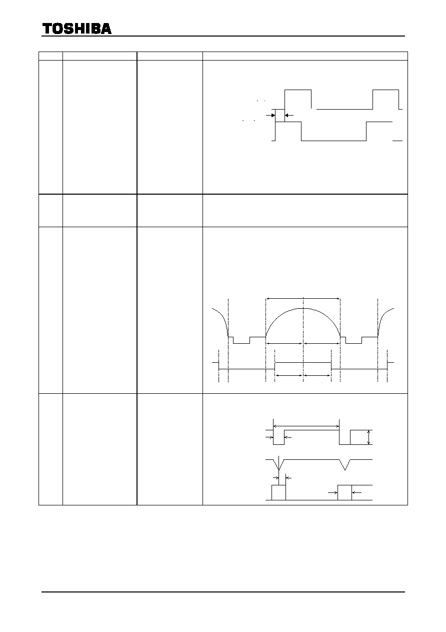
D12
Horizontal
Position
Variable Range
/ ΔPHHPOS
/ ΔPHHCOR+
/ ΔPHHCOR
-
H
Position:0/31
Others: Preset
(1) Input a composite sync signal into Pin61.
(2) Changing BUS data of “Horizontal Position” from 0 to 31,
measure "ΔPHHPOS" according to the following figure.
FBP in(Pin37)
(00)
(1F)
ΔPH
HPOS
(3) Measure the H phase where the pin #73 (Hcorr) is opened
and the HPOS is 16
(4) Measure the H phase shift form (3) when supply 5.5V for
pin #73, that isΔPHHCOR+.
(5) Measure the H phase shift from (3) when supply 0.5V for
pin #73, that isΔPHHCOR-.
D13
AFC-2 Pulse
Threshold Level
/ VAFC2
All: Preset
(1) Input a composite sync signal into Pin61.
(2) Decreasing the FBP high level, measure the DC level at
which H OUT phase changes against Sync in(Pin61)
phase, that is "VAFC2".
D14
H-BLK Pulse
Threshold Level
/ VHBLK
Δ
WWHBLK50L
Δ
WWHBLK50R
Δ
WWHBLK60L
Δ
WWHBLK60R
RGB Mute:0
contrast:127
Others: Preset
(1) Input a composite sync signal into Pin61.
(2) Increasing the FBP high level, measure the DC level at
which H blanking begins to work, that is "VHBLK".
(3) Measure as the figure below when the IICBUS of
'W-HBLK=1' and when input 50/60Hz of V freq.
100%
WIDE
H-BLK
Δwhblk50L
Δwhblk60L
Δwhblk50R
Δwhblk60R
D15
Black Peak Det. Stop
Period (H)
/ PHBPDET
/ WBPDET
TEST:00001000
Black Stretch:01
Others: Preset
(1) Input a composite sync signal into Pin61.
(2) According to the following figure, measure "PHBPDET" &
"WBPDET".
Sync in(Pin61)
H AFC(Pin43)
SCP OUT(Pin37)
63.5
s
4.7
s
ΔPH
HPOS
W
BPDET
5V
0V
0.25V
相关PDF资料 |
PDF描述 |
|---|---|
| TB1274BFG | SPECIALTY CONSUMER CIRCUIT, PQFP48 |
| TB1305FG | SYNC SEPARATOR IC, PQFP48 |
| TB1308FG | SYNC SEPARATOR IC, PQFP48 |
| TB1308FG | SYNC SEPARATOR IC, PQFP48 |
| TB1305FG | SYNC SEPARATOR IC, PQFP48 |
相关代理商/技术参数 |
参数描述 |
|---|---|
| TB1262F | 制造商:TOSHIBA 制造商全称:Toshiba Semiconductor 功能描述:TOSHIBA BiCMOS INTEGRATED CIRCUIT, SILICON MONOLITHIC |
| TB1274BFG | 制造商:TOSHIBA 制造商全称:Toshiba Semiconductor 功能描述:LUMINANCE, CHROMA AND SYNCHRONIZING SIGNALS PROCESSOR IC FOR PAL / NTSC / SECAM COLOR TV |
| TB12A | 制造商:Lenline 功能描述: |
| TB12A6C | 制造商:STMicroelectronics 功能描述:TB12A6C - Rail/Tube |
| TB12C6CM | 制造商:STMicroelectronics 功能描述:TB12C6CM - Rail/Tube |
发布紧急采购,3分钟左右您将得到回复。