- 您现在的位置:买卖IC网 > PDF目录98167 > TC110503ECT 0.1 A SWITCHING CONTROLLER, 345 kHz SWITCHING FREQ-MAX, PDSO5 PDF资料下载
参数资料
| 型号: | TC110503ECT |
| 元件分类: | 稳压器 |
| 英文描述: | 0.1 A SWITCHING CONTROLLER, 345 kHz SWITCHING FREQ-MAX, PDSO5 |
| 封装: | SOT-23A, 5 PIN |
| 文件页数: | 13/16页 |
| 文件大小: | 464K |
| 代理商: | TC110503ECT |

TC110
DS21355B-page 6
2002 Microchip Technology Inc.
3.5
Output Capacitor
The effective series resistance of the output capacitor
directly affects the amplitude of the output voltage
ripple. (The product of the peak inductor current and
the ESR determines output ripple amplitude.) There-
fore, a capacitor with the lowest possible ESR should
be selected. Smaller capacitors are acceptable for light
loads or in applications where ripple is not a concern.
The Sprague 595D series of tantalum capacitors are
among the smallest of all low ESR surface mount
capacitors
available.
Table 4-1
lists
suggested
components and suppliers.
3.6
Inductor Selection
Selecting the proper inductor value is a trade-off
between physical size and power conversion require-
ments. Lower value inductors cost less, but result in
higher ripple current and core losses. They are also
more prone to saturate since the coil current ramps
faster and could overshoot the desired peak value. This
not only reduces efficiency, but could also cause the
current rating of the external components to be
exceeded. Larger inductor values reduce both ripple
current and core losses, but are larger in physical size
and tend to increase the start-up time slightly.
A22
H inductor is recommended for the 300kHz
versions and a 47
H inductor is recommended for the
100kHz versions. Inductors with a ferrite core (or
equivalent) are
also
recommended. For highest
efficiency, use inductors with a low DC resistance (less
than 20 m
).
The inductor value directly affects the output ripple
voltage. Equation 3-3 is derived as shown below, and
can be used to calculate an inductor value, given the
required output ripple voltage and output capacitor
series resistance:
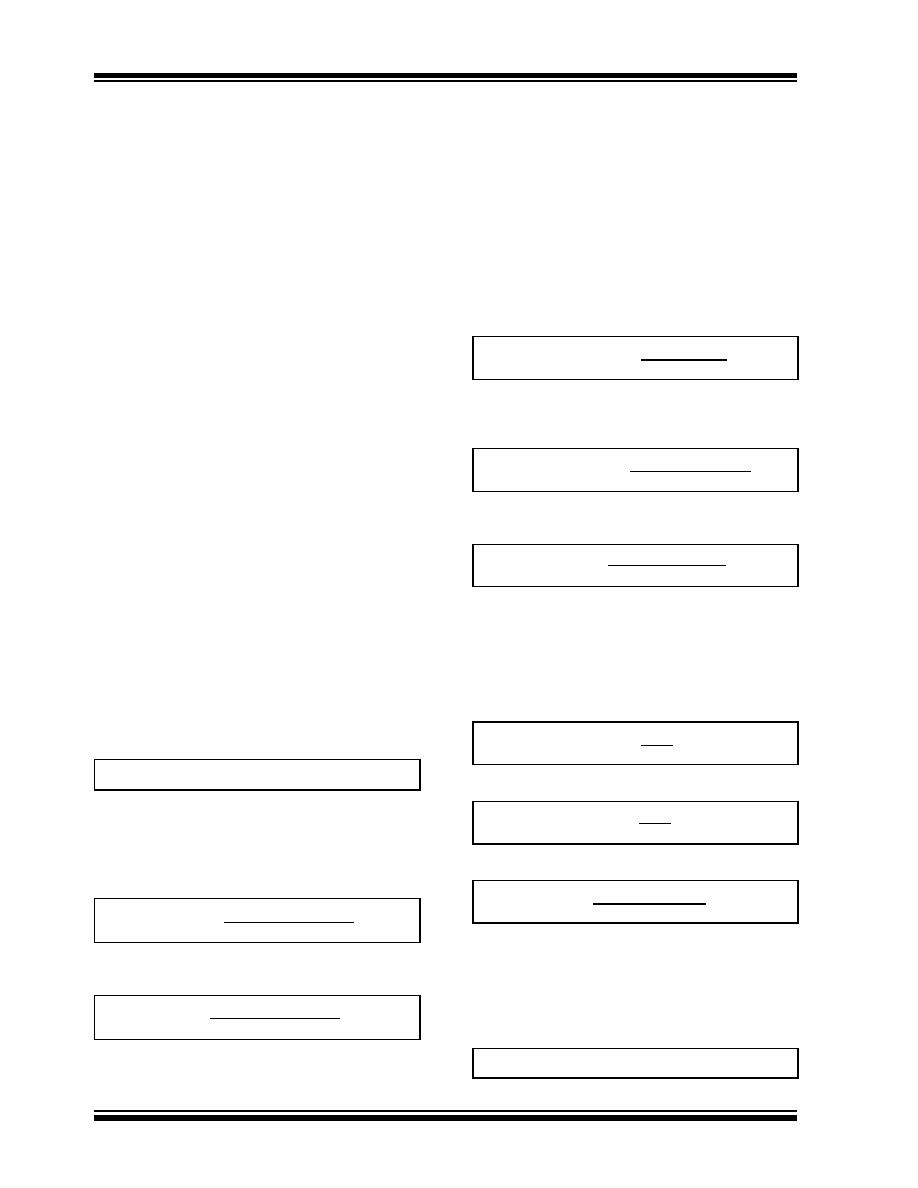
EQUATION 3-1:
where ESR is the equivalent series resistance of the
output filter capacitor, and VRIPPLE is in volts.
Expressing di in terms of switch ON resistance and
time:
EQUATION 3-2:
Solving for L:
EQUATION 3-3:
Care must be taken to ensure the inductor can handle
peak switching currents, which can be several times
load currents. Exceeding rated peak current will result
in core saturation and loss of inductance. The inductor
should be selected to withstand currents greater than
IPK (Equation 3-10) without saturating.
Calculating the peak inductor current is straightforward.
Inductor current consists of an AC (sawtooth) current
centered on an average DC current (i.e., input current).
Equation 3-6 calculates the average DC current. Note
that minimum input voltage and maximum load current
values should be used:
EQUATION 3-4:
Re-writing in terms of input and output currents and
voltages:
EQUATION 3-5:
Solving for input curent:
EQUATION 3-6:
The sawtooth current is centered on the DC current
level; swinging equally above and below the DC current
calculated in Equation 3-6. The peak inductor current is
the sum of the DC current plus half the AC current.
Note that minimum input voltage should be used when
calculating the AC inductor current (Equation 3-9).
EQUATION 3-7:
EQUATION 3-8:
EQUATION 3-9:
where: VSW =VCESAT of theswitch(note if aCMOS
switch is used substitute VCESAT for rDSON xIIN)
Combining the DC current calculated in Equation 3-6,
with half the peak AC current calculated in Equation 3-
9, the peak inductor current is given by:
EQUATION 3-10:
VRIPPLE ≈ ESR(di)
VRIPPLE ≈
ESR [(VIN –VSW)tON]
L
≈
ESR [(VIN –VSW)tON]
VRIPPLE
L
=
Output Power
Efficiency
Input Power
(VOUTMAX)(IOUTMAX)
Efficiency
(VINMIN)(IINMAX)=
(VOUTMAX)(IOUTMAX)
(Efficiency)(VINMAX)
IINMAX =
=
L(di)
dt
V
=
V(dt)
dt
di
[(VINMIN –VSW)tON]
L
di =
IPK =IINMAX +0.5(di)
相关PDF资料 |
PDF描述 |
|---|---|
| TC110301ECT | 0.1 A SWITCHING CONTROLLER, 115 kHz SWITCHING FREQ-MAX, PDSO5 |
| TC115501ECT | 0.4 A SWITCHING REGULATOR, 115 kHz SWITCHING FREQ-MAX, PDSO5 |
| TC115301ECT | 0.4 A SWITCHING REGULATOR, 115 kHz SWITCHING FREQ-MAX, PDSO5 |
| TC1219ECHTR | SWITCHED CAPACITOR CONVERTER, 20 kHz SWITCHING FREQ-MAX, PDSO6 |
| TC126301ECT | 0.4 A SWITCHING REGULATOR, 115 kHz SWITCHING FREQ-MAX, PDSO5 |
相关代理商/技术参数 |
参数描述 |
|---|---|
| TC110503ECTTR | 功能描述:开关变换器、稳压器与控制器 PFM/PWM Step-Up RoHS:否 制造商:Texas Instruments 输出电压:1.2 V to 10 V 输出电流:300 mA 输出功率: 输入电压:3 V to 17 V 开关频率:1 MHz 工作温度范围: 安装风格:SMD/SMT 封装 / 箱体:WSON-8 封装:Reel |
| TC1106D-120M | 制造商:PRODUCTWELL 制造商全称:PRODUCTWELL 功能描述:TOROID INDUCTORS |
| TC1107 | 制造商:MICROCHIP 制造商全称:Microchip Technology 功能描述:300mA CMOS LDO with Shutdown and VREF Bypass |
| TC1107_13 | 制造商:MICROCHIP 制造商全称:Microchip Technology 功能描述:300mA CMOS LDO with Shutdown and VREF Bypass |
| TC1107-2.5VOA | 功能描述:低压差稳压器 - LDO 300mA LDO w/Shdn RoHS:否 制造商:Texas Instruments 最大输入电压:36 V 输出电压:1.4 V to 20.5 V 回动电压(最大值):307 mV 输出电流:1 A 负载调节:0.3 % 输出端数量: 输出类型:Fixed 最大工作温度:+ 125 C 安装风格:SMD/SMT 封装 / 箱体:VQFN-20 |
发布紧急采购,3分钟左右您将得到回复。