- 您现在的位置:买卖IC网 > PDF目录68032 > TC1304-ZQ1EMF 0.5 A SWITCHING REGULATOR, 2400 kHz SWITCHING FREQ-MAX, PDSO10 PDF资料下载
参数资料
| 型号: | TC1304-ZQ1EMF |
| 元件分类: | 稳压器 |
| 英文描述: | 0.5 A SWITCHING REGULATOR, 2400 kHz SWITCHING FREQ-MAX, PDSO10 |
| 封装: | 3 X 3 MM, 0.9 MM HEIGHT, PLASTIC, DFN-10 |
| 文件页数: | 19/38页 |
| 文件大小: | 756K |
| 代理商: | TC1304-ZQ1EMF |
第1页第2页第3页第4页第5页第6页第7页第8页第9页第10页第11页第12页第13页第14页第15页第16页第17页第18页当前第19页第20页第21页第22页第23页第24页第25页第26页第27页第28页第29页第30页第31页第32页第33页第34页第35页第36页第37页第38页
TC1303A/TC1303B/TC1303C/TC1304
DS21949C-page 26
2008 Microchip Technology Inc.
5.5
Inductor Selection
For most applications, a 4.7 H inductor is recom-
mended to minimize noise. There are many different
magnetic core materials and package options to select
from. That decision is based on size, cost and accept-
able radiated energy levels. Toroid and shielded ferrite
pot cores will have low radiated energy, but tend to be
larger and higher is cost. With a typical 2.0 MHz
switching frequency, the inductor ripple current can be
calculated based on the following formulas.
EQUATION 5-2:
Duty cycle represents the percentage of switch-on
time.
EQUATION 5-3:
The inductor ac ripple current can be calculated using
the following relationship:
EQUATION 5-4:
Solving for IL = yields:
EQUATION 5-5:
When considering inductor ratings, the maximum DC
current rating of the inductor should be at least equal to
the maximum buck regulator load current (IOUT1), plus
one half of the peak-to-peak inductor ripple current (1/
2*
ΔIL). The inductor DC resistance can add to the
buck converter I2R losses. A rating of less than 200 m
is recommended. Overall efficiency will be improved by
using lower DC resistance inductors.
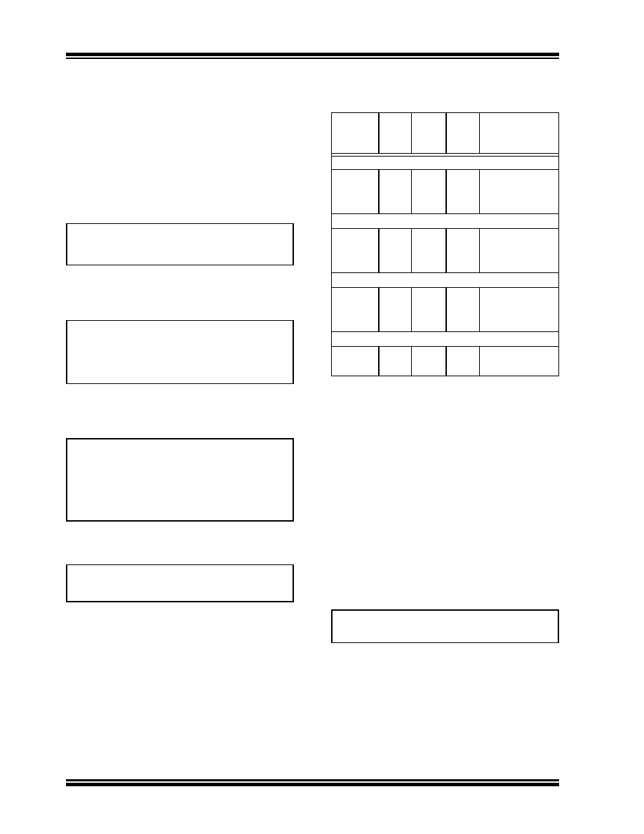
TABLE 5-2:
TC1303A, TC1303B, TC1303C,
TC1304 RECOMMENDED
INDUCTOR VALUES
5.6
Thermal Calculations
5.6.1
BUCK REGULATOR OUTPUT
(VOUT1)
The TC1303/TC1304 is available in two different 10-pin
packages (MSOP and 3x3 DFN). By calculating the
power dissipation and applying the package thermal
resistance, (
θJA), the junction temperature is estimated.
The maximum continuous junction temperature rating
for the TC1303/TC1304 is +125°C.
To quickly estimate the internal power dissipation for
the switching buck regulator, an empirical calculation
using measured efficiency can be used. Given the
measured efficiency (Section 2.0 “Typical Perfor-
mance Curves”), the internal power dissipation is
estimated below:
EQUATION 5-6:
The first term is equal to the input power (definition of
efficiency, POUT/PIN = Efficiency). The second term is
equal to the delivered power. The difference is internal
power dissipation. This is an estimate assuming that
most of the power lost is internal to the TC1303B.
There is some percentage of power lost in the buck
inductor, with very little loss in the input and output
capacitors.
DutyCycle
V
OUT
V
IN
-------------
=
T
ON
DutyCycle
1
F
SW
----------
×
=
Where:
FSW = Switching Frequency.
V
L
ΔI
L
Δt
--------
×
=
Where:
VL = voltage across the inductor (VIN – VOUT)
t = on-time of P-channel MOSFET
ΔI
L
V
L
------
Δt
×
=
Part
Number
Value
(H)
DCR
(MAX)
MAX
IDC (A)
Size
WxLxH (mm)
Coiltronics
SD10
2.2
0.091
1.35 5.2, 5.2, 1.0 max.
SD10
3.3
0.108
1.24 5.2, 5.2, 1.0 max.
SD10
4.7
0.154
1.04 5.2, 5.2, 1.0 max.
Coiltronics
SD12
2.2
0.075
1.80 5.2, 5.2, 1.2 max.
SD12
3.3
0.104
1.42 5.2, 5.2, 1.2 max.
SD12
4.7
0.118
1.29 5.2, 5.2, 1.2 max.
Sumida Corporation
CMD411
2.2
0.116
0.950 4.4, 5.8, 1.2 max.
CMD411
3.3
0.174 0.770 4.4, 5.8, 1.2 max.
CMD411
4.7
0.216 0.750 4.4, 5.8, 1.2 max.
Coilcraft
1008PS
4.7
0.35
1.0
3.8, 3.8, 2.74 max.
1812PS
4.7
0.11
1.15 5.9, 5.0, 3.81 max
V
OUT1
I
OUT1
×
Efficiency
-------------------------------------
V
OUT1
I
OUT1
×
()
–
P
Dissipation
=
相关PDF资料 |
PDF描述 |
|---|---|
| TC1304-ZS3EUNTR | 0.5 A SWITCHING REGULATOR, 2400 kHz SWITCHING FREQ-MAX, PDSO10 |
| TC1303A-1C3EUNTR | 0.5 A SWITCHING REGULATOR, 2400 kHz SWITCHING FREQ-MAX, PDSO10 |
| TC1303A-1D1EMFTR | 0.5 A SWITCHING REGULATOR, 2400 kHz SWITCHING FREQ-MAX, PDSO10 |
| TC1303A-1E3EMF | 0.5 A SWITCHING REGULATOR, 2400 kHz SWITCHING FREQ-MAX, PDSO10 |
| TC1303A-1H1EMFTR | 0.5 A SWITCHING REGULATOR, 2400 kHz SWITCHING FREQ-MAX, PDSO10 |
相关代理商/技术参数 |
参数描述 |
|---|---|
| TC1304-ZS0EMF | 功能描述:低压差稳压器 - LDO PWM/LDO combo/seq RoHS:否 制造商:Texas Instruments 最大输入电压:36 V 输出电压:1.4 V to 20.5 V 回动电压(最大值):307 mV 输出电流:1 A 负载调节:0.3 % 输出端数量: 输出类型:Fixed 最大工作温度:+ 125 C 安装风格:SMD/SMT 封装 / 箱体:VQFN-20 |
| TC1304-ZS0EMFTR | 功能描述:低压差稳压器 - LDO PWM/LDO combo/seq RoHS:否 制造商:Texas Instruments 最大输入电压:36 V 输出电压:1.4 V to 20.5 V 回动电压(最大值):307 mV 输出电流:1 A 负载调节:0.3 % 输出端数量: 输出类型:Fixed 最大工作温度:+ 125 C 安装风格:SMD/SMT 封装 / 箱体:VQFN-20 |
| TC1304-ZS0EUN | 功能描述:低压差稳压器 - LDO PWM/LDO combo/seq RoHS:否 制造商:Texas Instruments 最大输入电压:36 V 输出电压:1.4 V to 20.5 V 回动电压(最大值):307 mV 输出电流:1 A 负载调节:0.3 % 输出端数量: 输出类型:Fixed 最大工作温度:+ 125 C 安装风格:SMD/SMT 封装 / 箱体:VQFN-20 |
| TC1304-ZS0EUNTR | 功能描述:低压差稳压器 - LDO PWM/LDO combo/seq RoHS:否 制造商:Texas Instruments 最大输入电压:36 V 输出电压:1.4 V to 20.5 V 回动电压(最大值):307 mV 输出电流:1 A 负载调节:0.3 % 输出端数量: 输出类型:Fixed 最大工作温度:+ 125 C 安装风格:SMD/SMT 封装 / 箱体:VQFN-20 |
| TC1305R-DVUN | 功能描述:低压差稳压器 - LDO Dual LDO w/ Sdn RoHS:否 制造商:Texas Instruments 最大输入电压:36 V 输出电压:1.4 V to 20.5 V 回动电压(最大值):307 mV 输出电流:1 A 负载调节:0.3 % 输出端数量: 输出类型:Fixed 最大工作温度:+ 125 C 安装风格:SMD/SMT 封装 / 箱体:VQFN-20 |
发布紧急采购,3分钟左右您将得到回复。