- 您现在的位置:买卖IC网 > PDF目录69481 > TC646VUA BRUSHLESS DC MOTOR CONTROLLER, PDSO8 PDF资料下载
参数资料
| 型号: | TC646VUA |
| 元件分类: | 运动控制电子 |
| 英文描述: | BRUSHLESS DC MOTOR CONTROLLER, PDSO8 |
| 封装: | PLASTIC, MSOP-8 |
| 文件页数: | 3/28页 |
| 文件大小: | 473K |
| 代理商: | TC646VUA |
第1页第2页当前第3页第4页第5页第6页第7页第8页第9页第10页第11页第12页第13页第14页第15页第16页第17页第18页第19页第20页第21页第22页第23页第24页第25页第26页第27页第28页
2002 Microchip Technology Inc.
DS21446C-page 11
TC646
5.1
Temperature Sensor Design
The temperature signal connected to VIN must output a
voltage in the range of 1.25V to 2.65V (typical) for 0%
to 100% of the temperature range of interest. The
circuit in Figure 5-2 illustrates a convenient way to
provide this signal.
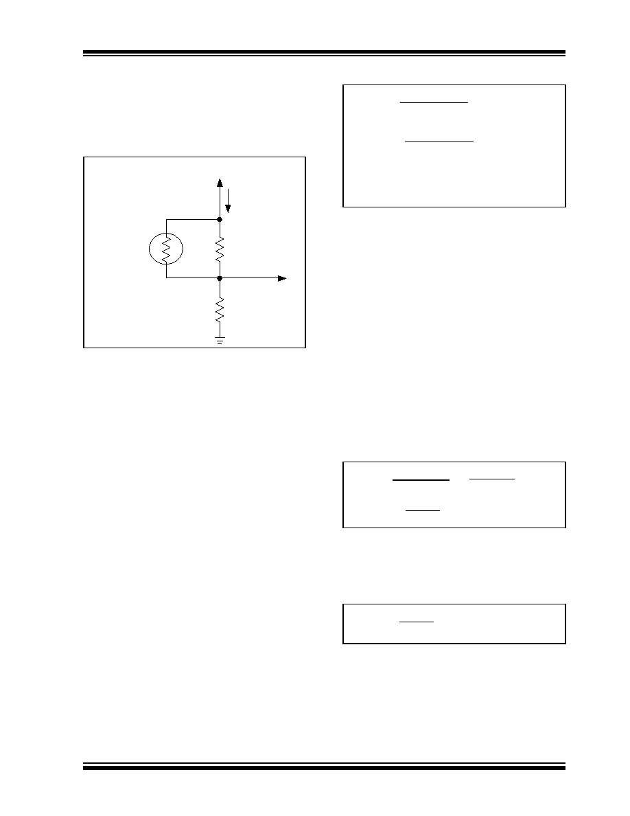
FIGURE 5-2:
Temperature Sensing
Circuit.
Figure 5-2 shows a simple temperature dependent
voltage divider circuit. RT1 is a conventional NTC ther-
mistor, while R1 and R2 are standard resistors. The
supply voltage, VDD, is divided between R2 and the
parallel combination of RT1 and R1. For convenience,
the parallel combination of RT1 and R1 will be referred
to as RTEMP. The resistance of the thermistor at various
temperatures is obtained from the manufacturer’s
specifications. Thermistors are often referred to in
terms of their resistance at 25°C.
Generally, the thermistor shown in Figure 5-2 is a non-
linear device with a negative temperature coefficient
used to linearize the thermistor temperature response
and R2 is used to produce a positive temperature
coefficient at the VIN node. As an added benefit, this
configuration produces an output voltage delta of 1.4V,
which is well within the range of the VC(SPAN)
specification of the TC646. A 100 k
NTC thermistor is
selected for this application in order to keep IDIV at a
minimum.
For the voltage range at VIN to be equal to 1.25V to
2.65V, the temperature range of this configuration is
0°C to 50°C. If a different temperature range is required
from this circuit, R1 should be chosen to equal the
resistance value of the thermistor at the center of this
new temperature range. It is suggested that a maxi-
mum temperature range of 50°C be used with this cir-
cuit due to thermistor linearity limitations. With this
change, R2 is adjusted according to the following
equations:
EQUATION
These two equations facilitate solving for the two
unknown variables, R1 and R2. More information about
thermistors may be obtained from AN679, “Tempera-
ture Sensing Technologies”, and AN685, “Thermistors
In Single Supply Temperature Sensing Circuits”, which
can be downloaded from Microchip’s web site at
www.microchip.com.
5.2
Auto-Shutdown Temperature
Design
A voltage divider on VAS sets the temperature where
the part is automatically shut down if the sensed
temperature at VIN drops below the set temperature at
VAS (i.e., VIN < VAS). As with the VIN input, 1.25V to
2.65V corresponds to the temperature range of interest
from T1 to T2, respectively. Assuming that the
temperature sensor network designed above is linearly
related to temperature, the shutdown temperature TAS
is related to T2 and T1 by:
EQUATION
For example, if 1.25V and 2.65V at VIN corresponds to
a temperature range of T1 = 0°C to T2 = 125°C, and the
auto-shutdown temperature desired is 25°C, then VAS
voltage is:
EQUATION
The VAS voltage may be set using a simple resistor
divider as shown in Figure 5-3.
R2 = 23.2k
R1 = 100 k
NTC Thermistor
100 k
@25C
IDIV
VIN
VDD
RT1
VDD x R2
RTEMP (T1) + R2
= V(T1)
RTEMP (T2) + R2
= V(T2)
VDD x R2
Where T1 and T2 are the chosen temperatures and
RTEMP is the parallel combination of the thermistor
and R1.
2.65V - 1.25V
T2 - T1
=
VAS - 1.25V
TAS - T1
VAS =
(
( TAS - T1) + 1.25V
1.4V
)
T2 - T1
VAS =
(25 - 0) + 1.25V = 1.53V
1.4V
(125 - 0)
相关PDF资料 |
PDF描述 |
|---|---|
| TC646VOA713G | BRUSHLESS DC MOTOR CONTROLLER, PDSO8 |
| TC646VOA713 | BRUSHLESS DC MOTOR CONTROLLER, PDSO8 |
| TC646EOA713 | BRUSHLESS DC MOTOR CONTROLLER, PDSO8 |
| TC646VUA713 | BRUSHLESS DC MOTOR CONTROLLER, PDSO8 |
| TC646VOA | BRUSHLESS DC MOTOR CONTROLLER, PDSO8 |
相关代理商/技术参数 |
参数描述 |
|---|---|
| TC646VUA713 | 功能描述:马达/运动/点火控制器和驱动器 Shtdn & Fault Dtct RoHS:否 制造商:STMicroelectronics 产品:Stepper Motor Controllers / Drivers 类型:2 Phase Stepper Motor Driver 工作电源电压:8 V to 45 V 电源电流:0.5 mA 工作温度:- 25 C to + 125 C 安装风格:SMD/SMT 封装 / 箱体:HTSSOP-28 封装:Tube |
| TC647 | 制造商:MICROCHIP 制造商全称:Microchip Technology 功能描述:PWM Fan Speed Controller with FanSense Technology |
| TC647_13 | 制造商:MICROCHIP 制造商全称:Microchip Technology 功能描述:PWM Fan Speed Controller with FanSensea?¢ Technology |
| TC647B | 制造商:MICROCHIP 制造商全称:Microchip Technology 功能描述:PWM Fan Speed Controllers With Minimum Fan Speed, Fan Restart and FanSense⑩ Technology for Fault Detection |
| TC647BEOA | 功能描述:马达/运动/点火控制器和驱动器 w/Rstrt & Flt Dtct RoHS:否 制造商:STMicroelectronics 产品:Stepper Motor Controllers / Drivers 类型:2 Phase Stepper Motor Driver 工作电源电压:8 V to 45 V 电源电流:0.5 mA 工作温度:- 25 C to + 125 C 安装风格:SMD/SMT 封装 / 箱体:HTSSOP-28 封装:Tube |
发布紧急采购,3分钟左右您将得到回复。