- 您现在的位置:买卖IC网 > PDF目录98170 > TC648BEOA BRUSHLESS DC MOTOR CONTROLLER, PDSO8 PDF资料下载
参数资料
| 型号: | TC648BEOA |
| 元件分类: | 运动控制电子 |
| 英文描述: | BRUSHLESS DC MOTOR CONTROLLER, PDSO8 |
| 封装: | 0.150 INCH, PLASTIC, SOIC-8 |
| 文件页数: | 10/36页 |
| 文件大小: | 704K |
| 代理商: | TC648BEOA |
第1页第2页第3页第4页第5页第6页第7页第8页第9页当前第10页第11页第12页第13页第14页第15页第16页第17页第18页第19页第20页第21页第22页第23页第24页第25页第26页第27页第28页第29页第30页第31页第32页第33页第34页第35页第36页
TC646B/TC648B/TC649B
DS21755B-page 18
2003 Microchip Technology Inc.
5.0
APPLICATIONS INFORMATION
5.1
Setting the PWM Frequency
The PWM frequency of the VOUT output is set by the
capacitor value attached to the CF pin. The PWM fre-
quency will be 30 Hz (typical) for a 1 F capacitor. The
relationship between frequency and capacitor value is
linear, making alternate frequency selections easy.
As stated in previous sections, the PWM frequency
should be kept in the range of 15 Hz to 35 Hz. This will
eliminate the possibility of having audible frequencies
when varying the duty cycle of the fan drive.
A very important factor to consider when selecting the
PWM frequency for the TC646B/TC648B/TC649B
devices is the RPM rating of the selected fan and the
minimum duty cycle that you will be operating at. For
fans that have a full-speed rating of 3000 RPM or less,
it is desirable to use a lower PWM frequency. A lower
PWM frequency allows for a longer time-period to mon-
itor the fan current pulses. The goal is to be able to
monitor at least two fan current pulses during the on-
time of the VOUT output.
Example: The system design requirement is to operate
the fan at 50% duty cycle when ambient temperatures
are below 20°C. The fan full-speed RPM rating is
3000 RPM and has four current pulses per rotation. At
50% duty cycle, the fan will be operating at
approximately 1500 RPM.
EQUATION
If one fan revolution occurs in 40 msec, each fan pulse
occurs 10 msec apart. In order to detect two fan current
pulses, the on-time of the VOUT pulse must be at least
20 msec. With the duty cycle at 50%, the total period of
one cycle must be at least 40 msec, which makes the
PWM frequency 25 Hz. For this example, a PWM fre-
quency of 20 Hz is recommended. This would define a
CF capacitor value of 1.5 F.
5.2
Temperature Sensor Design
As discussed in previous sections, the VIN analog input
has a range of 1.20V to 2.60V (typical), which repre-
sents a duty cycle range on the VOUT output of 0% to
100%, respectively. The VIN voltages can be thought of
as representing temperatures. The 1.20V level is the
low temperature at which the system requires very little
cooling. The 2.60V level is the high temperature, for
which the system needs maximum cooling capability
(100% fan speed).
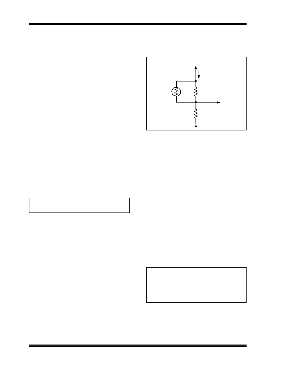
One of the simplest ways of sensing temperature over
a given range is to use a thermistor. By using a NTC
thermistor, as shown in Figure 5-1, a temperature-
variant voltage can be created.
FIGURE 5-1:
Temperature Sensing
Circuit.
Figure 5-1 represents a temperature-dependent, volt-
age divider circuit. RT is a conventional NTC thermistor,
R1 and R2 are standard resistors. R1 and RT form a
parallel resistor combination that will be referred to as
RTEMP (RTEMP = R1 * RT / R1 + RT). As the temperature
increases, the value of RT decreases and the value of
RTEMP will decrease with it. Accordingly, the voltage at
VIN increases as temperature increases, giving the
desired relationship for the VIN input. R1 helps to linear-
ize the response of the SENSE network and aids in
obtaining the proper VIN voltages over the desired tem-
perature range. An example of this is shown in
If less current draw from VDD is desired, a larger value
thermistor should be chosen. The voltage at the VIN pin
can also be generated by a voltage output temperature
sensor device. The key is to get the desired VIN volt-
age-to-system (or component) temperature relation-
ship.
The following equations apply to the circuit in
EQUATION
In order to solve for the values of R1, R2, VIN and the
temperatures at which they are to occur, need to be
selected. The variables T1 and T2 represent the
selected temperatures. The value of the thermistor at
these two temperatures can be found in the thermistor
Time for one revolution (msec.)
60 1000
×
1500
------------------------40
==
R2
R1
RT
IDIV
VIN
VDD
VT1
()
VDD R2
×
RTEMP T1
() R2
+
----------------------------------------------
=
VT2
()
VDD R2
×
RTEMP T2
() R2
+
----------------------------------------------
=
相关PDF资料 |
PDF描述 |
|---|---|
| TC649BEUATR | BRUSHLESS DC MOTOR CONTROLLER, PDSO8 |
| TC646BEOA713 | BRUSHLESS DC MOTOR CONTROLLER, PDSO8 |
| TC649VOART | BRUSHLESS DC MOTOR CONTROLLER, PDSO8 |
| TC649VUATR | BRUSHLESS DC MOTOR CONTROLLER, PDSO8 |
| TC649VOATR | BRUSHLESS DC MOTOR CONTROLLER, PDSO8 |
相关代理商/技术参数 |
参数描述 |
|---|---|
| TC648BEOA713 | 功能描述:马达/运动/点火控制器和驱动器 Shtdn & Over-T Alert RoHS:否 制造商:STMicroelectronics 产品:Stepper Motor Controllers / Drivers 类型:2 Phase Stepper Motor Driver 工作电源电压:8 V to 45 V 电源电流:0.5 mA 工作温度:- 25 C to + 125 C 安装风格:SMD/SMT 封装 / 箱体:HTSSOP-28 封装:Tube |
| TC648BEOAG | 制造商:Microchip Technology 功能描述:PWM Fan Motor Speed Controller 8-Pin SOIC N Tube |
| TC648BEOATR | 制造商:MICROCHIP 制造商全称:Microchip Technology 功能描述:PWM Fan Speed Controllers With Auto-Shutdown, Fan Restart and FanSense⑩ Technology for Fault Detection |
| TC648BEPA | 功能描述:马达/运动/点火控制器和驱动器 Shtdn & Over-T Alert RoHS:否 制造商:STMicroelectronics 产品:Stepper Motor Controllers / Drivers 类型:2 Phase Stepper Motor Driver 工作电源电压:8 V to 45 V 电源电流:0.5 mA 工作温度:- 25 C to + 125 C 安装风格:SMD/SMT 封装 / 箱体:HTSSOP-28 封装:Tube |
| TC648BEPA713 | 制造商:MICROCHIP 制造商全称:Microchip Technology 功能描述:PWM Fan Speed Controllers With Auto-Shutdown, Fan Restart and FanSense⑩ Technology for Fault Detection |
发布紧急采购,3分钟左右您将得到回复。